
Linpeng Yu, Jinhui Liang, Shiting Huang, Jinzhang Wang, Jiachen Wang, Xing Luo, Peiguang Yan, Fanlong Dong, Xing Liu, Qitao Lue, Chunyu Guo, Shuangchen Ruan. Generation of single solitons tunable from 3 to 3.8 μ m in cascaded Er3+-doped and Dy3+-doped fluoride fiber amplifiers[J]. Photonics Research, 2022, 10(9): 2140
- Photonics Research
- Vol. 10, Issue 9, 2140 (2022)
Abstract
1. INTRODUCTION
High-power femtosecond mid-infrared (MIR) laser radiation is of vast importance due to its wide applications ranging from molecular spectroscopy, remote sensing, laser surgery, and material processing [1–4]. Compared to solid-state lasers, fiber-based MIR femtosecond lasers have clear advantages in terms of compactness, inherently high beam quality, and environmental reliability. Mode-locking of rare-earth-doped fluoride fiber lasers is an effective technique for MIR femtosecond pulses generation. However, the mode-locked pulses are limited to a few wavelengths of [5,6], [7], [8], and [9], while the wavelength tunability is restricted by the rare-earth gain bandwidth. For a number of spectroscopic and sensing applications, MIR femtosecond laser sources with continuous tunability over a wide spectral range are required.
The soliton self-frequency shift (SSFS) [10] in optical fibers can be utilized to overcome the spectral limitation and provide femtosecond pulses with wide spectral tunability. The SSFS effect also has the advantage of cleaning up the main soliton from Kelly sidebands resulting in a very clean soliton [11]. Until now, SSFS-based tunable MIR femtosecond laser sources have been intensively studied during the last years in silica fibers [12], tellurite fibers [13], fluoride fibers [14,15], and chalcogenide fibers [16]. Raman solitons from silica fibers have a wavelength limitation due to the loss arising in the MIR region, while soft-glass fibers with low phonon energies can support Raman solitons shifting further into the MIR. Compared with tellurite and chalcogenide fibers, fluoride fibers possess a relatively low nonlinear refractive index and large anomalous dispersion, which enable the generation of Raman solitons with high pulse energy and high peak power.
Based on the SSFS effect in fluoride fibers, Tang
Sign up for Photonics Research TOC. Get the latest issue of Photonics Research delivered right to you!Sign up now
Recently, dysprosium has attracted increasing attention for its extremely broad emission cross section, which has enabled lasing from 2.8 to 3.4 μm [21]. More importantly, -doped fluoride fibers can be in-band pumped by the well-developed high-power -doped fluoride fiber lasers operating around 2.8 μm [8,22]. Such an in-band pumping scheme significantly reduces the pump-signal quantum defect, allowing Stokes efficiencies to reach 91% [23]. Therefore, there arises a probability that by cascading a piece of Dy:ZBLAN fiber to an SSFS-based laser system in which pump pulses at 2.8 μm are used to generate Raman solitons around 3 μm, the residual 2.8 μm radiation will be absorbed and recycled to amplify the incoming Raman solitons within the dysprosium gain bandwidth (). In this way, single Raman solitons with a higher energy conversion efficiency, a wider shifting range, and a higher average power can be expected.
In this paper, we demonstrate a fluoride-fiber-based system that generates single femtosecond solitons tunable from 3 to 3.8 μm. The system is composed of an -doped fluoride fiber oscillator followed by cascaded -doped and -doped fluoride fiber amplifiers. The -doped fluoride fiber amplifier is used not only to boost up the power of 2.8 μm femtosecond seed laser, but also to generate the SSFS up to 3 μm. The Raman solitons as well as the residual 2.8 μm radiation are then injected into the -doped fluoride fiber amplifier, in which the residual 2.8 μm radiation is absorbed and used to amplify the Raman solitons as long as the Raman solitons lie within the dysprosium gain bandwidth. What is more, the SSFS in the -doped fluoride fiber enables extension of the wavelength up to 3.8 μm. The output pulses only consist of the main shifted Raman solitons without any residual 2.8 μm radiation or secondary solitons. Stable 252 fs pulses at 3.8 μm with a record average power of 1.6 W and a pulse energy of 23 nJ are generated. This study provides an effective way to generate high-power widely tunable femtosecond MIR pulses with high spectral purity. Furthermore, the method of recycling the residual pump radiation to amplify the Raman solitons can be applied to other SSFS-based laser systems for the generation of single solitons.
2. EXPERIMENTAL SETUP
Figure 1 shows the schematic of the laser system, which consists of a femtosecond mode-locked oscillator and cascaded amplifiers. In the seed oscillator, a 2.4 m long 7% (atomic fraction) -doped double-cladding ZBLAN fiber (Le Verre Fluoré) which has a core diameter of 15 μm (NA = 0.12) surrounded by a truncated 260 μm diameter inner cladding (), is used as the gain medium. To prevent fiber tip degradation and damage under prolonged operation, a -based fiber endcap is spliced to the output end. The endcap is long with a 200 μm core size from Le Verre Fluoré. Both the endcap and the input fiber end are cleaved at an angle of 8° to suppress parasitic lasing. The gain fiber is pumped by a 976 nm diode laser with a pigtail of 105 μm diameter (NA = 0.22). Two dichroic mirrors (DM1 and DM2, at 976 nm and at 2.8 μm) are used to combine and separate the 2.8 μm seed light and 976 nm pump light, respectively. Output pulses are obtained from the output port of the polarization beam splitter. Self-starting mode-locking is achieved based on the nonlinear polarization rotation technique with the combination of a half-wave plate, a quarter-wave plate, and a polarization-dependent isolator (Thorlabs).
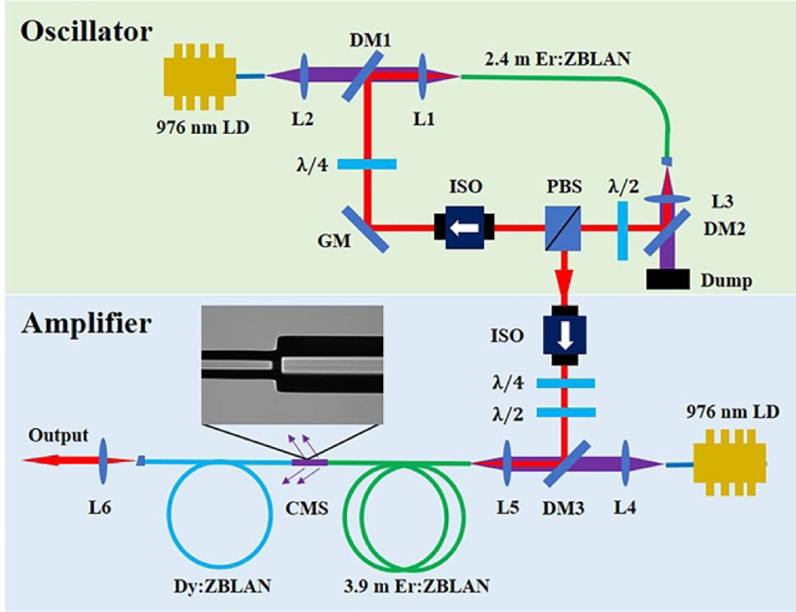
Figure 1.Schematic diagram of the laser system. DM, dichroic mirror; ISO, isolator; PBS, polarization beam splitter; LD, laser diode;
The mode-locked pulses then pass through another polarization-dependent isolator to block backward reflections from the amplifier. A quarter-wave plate and a half-wave plate are inserted before the amplifier to adjust the polarization of the signal pulse. After being combined by another DM, the signal and pump light are coupled into the -doped fluoride fiber amplifier, constituting a forward pumping configuration. The gain fiber is 3.9 m long with the same type of oscillator fiber. The -doped fluoride fiber amplifier is employed to act as both the amplifier for boosting the output power and the frequency shifter for realizing a Raman-induced SSFS. The Raman solitons together with the residual 2.8 μm radiation are then sent to the -doped fluoride fiber amplifier, while the residual 976 nm pump power is removed via a cladding mode stripper (CMS).
In the -doped fluoride fiber amplifier, single-cladding -doped fluorozirconate glass fibers (Le Verre Fluoré) with lengths of 1.2 and 11 m are used as the gain fibers, which have a core diameter of 12.5 μm, a cladding diameter of 125 μm, a numerical aperture of 0.16, and a -ion doping concentration of 0.2%. The -doped fluoride fiber is spliced to the -doped fluoride fiber. A microscope photograph of the fusion splice taken with the imaging systems of the Vytran GPX-3000 is shown in Fig. 1. Due to the slight mode mismatch between the two fibers, the maximum theoretical transmission through the splice is about 92%, while a maximum transmission of 82% is actually achieved in the experiment measured by cutback. The power lost through the splice is also removed by the CMS. The output fiber end of the gain fiber is spliced with an angle-cleaved endcap, the same type as above, to prevent fiber tips degradation at a high average power. In the -doped fluoride fiber amplifier, the residual 2.8 μm radiation is absorbed and used to amplify the Raman solitons as long as the Raman solitons lie within the dysprosium gain bandwidth, constituting an in-band pumping configuration. Moreover, the SSFS in the -doped fluoride fiber enables the extension of wavelength. The output beam from the amplifiers is collimated by a lens L6 () for measurements.
3. RESULTS AND DISCUSSION
A. Oscillator and
By carefully rotating the wave plates in the oscillator, self-starting mode-locking operation is achieved under a pump power of 2.5 W. Mode-locked pulses with an average power of 196 mW and a repetition rate of 69.65 MHz are obtained, corresponding to a pulse energy of 2.8 nJ. The spectrum is measured by an optical spectrum analyzer that covers the wavelength range from 1.5 to 3.4 μm (Yokogawa, AQ6376), as shown in Fig. 2(a). The central wavelength is located at 2.8 μm, while typical Kelly sidebands in the spectrum indicate that the laser operates in the soliton regime. The pulse duration is characterized using a commercial intensity autocorrelator (Femtochrome, FR-103 XL). The autocorrelation trace is presented in Fig. 2(b). Assuming a hyperbolic-secant pulse shape, the mode-locked pulse duration is 257 fs, corresponding to an estimated peak power of 10.9 kW. The radio-frequency (RF) spectrum in Fig. 2(c) exhibits a high signal-to-noise ratio (SNR) of at the fundamental frequency. Figure 2(d) shows the mode-locked pulse trains measured in 1 μs and 10 ms time scales, of which the remarkable regularity highlights the high temporal stability. The oscillator can operate stably without any manual alignment in 30 days when it is switched on and off every day, confirming the long-term stability.
![]()
Figure 2.(a) Output spectrum (black line) fitted with an ideal sech-shaped profile (red line), (b) autocorrelation trace fitted by a
The mode-locked seed light is then launched into the -doped fluoride fiber amplifier. Due to the transmission loss in the isolator and the coupling loss at the fiber end, the available signal pulse energy decreases to . Figure 3(a) shows the evolution of the output spectra. As the pump power is increased, a Raman soliton is formed and gradually shifts toward longer wavelengths, reaching a maximum central wavelength of 3.02 μm. As illustrated in Fig. 3(b), the central wavelengths of Raman solitons are slightly longer than the dysprosium emission cross section peak at 2880 nm, but still lie within the dysprosium gain bandwidth [21,24]. The total output power as a function of the incident pump power is shown in Fig. 3(b) (black squares). A slope efficiency of 23.7% is obtained by linear fitting. The average power contained within the Raman soliton is estimated using the spectral integral method and is also displayed in Fig. 3(b) (black triangles). Note that the average power and central wavelength of the Raman soliton are only given when the Raman soliton can be distinguished from the residual 2.8 μm background via the spectrum. The average power of the Raman soliton at 3.02 μm is 2.6 W, accounting for more than 60% of the total output average power of 4.1 W. Over the whole tuning range, more than 55% of the total energy is contained in the Raman soliton. A higher average power with a larger spectral shift is possible if the incident 976 nm pump power is further increased. However, it will cause a serious heat load at the CMS.
![]()
Figure 3.(a) Measured output spectra under different pump powers. (b) Average power and central wavelength of Raman solitons, and total output average power versus pump power.
It should be noted that the wave plate orientation is fixed regardless of the pump power, thus ensuring a same input polarization of the seed light. Since the input polarization has effects on the SSFS process [20], the output performance may differ when rotating the wave plates in the amplifier, which will be discussed in Section 3.C.
B. 1.2 m Long
The Raman solitons together with the residual 2.8 μm radiation are then injected into the -doped fluoride fiber amplifier. In order to test the amplification performance of the ultrashort Raman solitons under an in-band pumping scheme, a short gain fiber with a length of 1.2 m is chosen. Figure 4(a) depicts the output spectra at increasing 976 nm pump power levels. The spectra are taken using a Fourier-transform-based optical spectrum analyzer (Thorlabs, OSA205C). As the 976 nm pump power is increased from 7.9 to 20 W, the central wavelength of the Raman soliton can be continuously tuned from 2.94 to 3.29 μm. The spectral modulations are suspected to be caused by the measuring instruments. Compared with the output spectra from the -doped fluoride fiber amplifier in Fig. 3(a), the spectra in Fig. 4(a) have almost no spectral components at 2.8 μm, indicating an efficient absorption of the residual 2.8 μm radiation. The unabsorbed 2.8 μm radiation under a pump power of 7.9 W in the bottom panel of Fig. 4(a), which is caused by the low gain of the corresponding Raman soliton, can be cleaned with a longer -doped fluoride fiber. Furthermore, the Raman solitons experience a large spectral shift in the -doped fluoride fiber amplifier, but still lay within the dysprosium gain bandwidth. The spectral shift is mainly attributed to the SSFS in the fiber and the redshifted gain profile. Indeed, for an in-band pumping scheme, the gain profile is intrinsically dependent on the fiber length [8].
![]()
Figure 4.(a) The spectral evolution under different 976 nm pump powers in the 1.2 m long
Figure 4(b) shows the measured pulse duration and average power of the Raman solitons as a function of the 976 nm pump power. The pulse duration is characterized by a commercial second-harmonic generation frequency-resolved optical gating (SHG-FROG) device (Mesa Photonics, covering 2.5–4.0 μm). The SHG-FROG measurement error is below 0.6% in a grid size for each measurement, while error is acceptable as described in the SHG-FROG manual. The average power increases linearly with the 976 nm pump power without the appearance of saturation, reaching a maximum value of 2.9 W. The corresponding pulse energies of the Raman solitons are calculated and indicated on each spectrum of Fig. 4(a). As the 976 nm pump power increases, the pulse duration decreases slightly at first and then clamps around 100 fs. A clean isolated soliton at 3.29 μm with an average power of 2.9 W, a pulse energy of 42.2 nJ, and a pulse duration of 105 fs is obtained, corresponding to a peak power of 402 kW. The soliton order of the pulse can be calculated by
The amplification efficiency of Raman solitons in the amplifier is also calculated and displayed in Fig. 4(c). The amplification efficiency is defined as the ratio of the net increased Raman soliton power to the total residual 2.8 μm power. As shown in Fig. 4(c), the Raman solitons are indeed amplified, certificated by the increased pulse energy. An average amplification efficiency of more than 50% is obtained, highlighting the excellent potential for high-efficiency MIR fiber amplifiers using dysprosium. However, compared with the theoretical Stokes-limited efficiency of , the efficiency of 63% at 3.29 μm is somewhat lower. The difference is believed to be caused by the reabsorption of the Raman soliton and additional loss induced from the SSFS process. Further enhancement of the pulse energy can be expected by improving the splice point between the amplifiers or exploiting a continuous-wave 2.8 μm laser source to backward-pump the -doped fluoride fiber amplifier. Notably, this is the first demonstration of a -doped fluoride fiber amplifier to date. Given the large gain bandwidth of dysprosium, there is scope for few-cycle pulse generation from -based amplifiers.
C. 11 m Long
To shift the Raman solitons to a longer wavelength, a long gain fiber with a length of 11 m is used. Figure 5(a) shows the spectral evolution in the 11 m long -doped fluoride fiber amplifier. As the 976 nm pump power is increased from 7.9 to 20 W, the central wavelength of Raman solitons can be continuously tuned from 3.03 to 3.63 μm. No spectral components at 2.8 μm are observed in the spectra, as well as secondary solitons. The output spectra always keep a single-color Raman-soliton envelope, featuring a high spectral purity. The output average power increases with the 976 nm pump power, while the measured pulse duration decreases slightly at first and then clamps around 200 fs, as illustrated in Fig. 5(b). The corresponding pulse energies of the Raman solitons are calculated and indicated on each spectrum of Fig. 5(a). Compared with the Raman solitons from the 1.2 m long amplifier in Fig. 4(a), the Raman solitons from the 11 m long amplifier possess a larger spectral shift, a longer pulse duration, and a lower pulse energy under the same 976 nm pump power. The lost energy is due to the quantum defect during the SSFS process and the background loss of the fiber. The increased pulse duration should be attributed to the energy loss and the change of fiber dispersion and nonlinearity at longer wavelengths. The most redshifted Raman soliton located at 3.63 μm has a pulse energy of 31.8 nJ and a pulse duration of 210 fs, corresponding to a peak power of 151 kW. Interestingly, the soliton order is calculated to be 2.2 according to Eq. (1), meaning that the Raman soliton maintains a high-order soliton even though undergoing the large SSFS from 3.29 to 3.63 μm.
![]()
Figure 5.(a) Measured output spectra under different pump powers in the 11 m long
As pointed out by previous works, the Raman effect is sensitive to the input polarization state [28,29]. The central wavelength of Raman solitons can be tuned by changing the input polarization [20,30]. To further explore the wavelength tunability of this laser system, we accordingly carefully adjust the input polarization by rotating the wave plates in the cascaded amplifiers and record the output spectra. As shown in Fig. 6, the central wavelength of Raman solitons can be continuously tuned from 3.63 to 3.80 μm (covering 170 nm) under a pump power of 20 W, while the corresponding pulse energy decreases from 31.8 to 23 nJ and the pulse duration increases from 210 to 252 fs. The decreased energy should be mainly attributed to the rapidly increased background loss beyond 3.6 μm in fluorozirconate glass fibers. Employment of fluoroindate glass fibers with a low background loss in this wavelength range will enable a further extension of the wavelength.
![]()
Figure 6.Wavelength tunability and output characteristics of the 11 m long
Figures 7(a) and 7(b) display the measured and retrieved SHG-FROG traces of the Raman soliton at 3.8 μm, respectively. The reconstructed trace has an error of 0.35%. Figure 7(c) gives the retrieved spectrum, which is centered at 3.8 μm and has a 3 dB bandwidth of . For comparison, we have also independently measured the spectrum using the OSA205C. The good agreement between the measured and retrieved spectra confirms the validity of the SHG-FROG measurements. The retrieved temporal intensity and phase profiles shown in Fig. 7(d) yield a pulse duration of 252 fs. The time–bandwidth product is calculated to be 0.324, close to the Fourier-transform limit. According to the measured pulse energy of 23 nJ, the peak power is estimated to be 91 kW.
![]()
Figure 7.SHG-FROG measurements of the Raman soliton at 3.8 μm from the 11 m long
By simply varying the pump power and adjusting the signal polarization, single Raman solitons tunable from 3 to 3.8 μm are obtained. Compared with previous works in which the main shifted Raman solitons are always accompanied with nonshifted residual radiation or secondary solitons [14–16,30], output pulses from the cascaded configuration only consist of the main shifted Raman solitons. No more effort is required to filter out the undesired spectral components. Moreover, the cascaded configuration allows for the generation of femtosecond solitons with watt-level average power and pulse energies above 3.6 μm, which represent the best performances reported so far in terms of average power and pulse energy for a femtosecond fiber-based laser source.
D. Laser Noise Measurements
The system stability is important for the practical application of the Raman solitons. Therefore, it is essential to check the pulse operation state. We have characterized the output Raman solitons from the 11 m long -doped fluoride fiber amplifier under a pump power of 20 W. Figure 8(a) shows the measured RF spectrum at the fundamental frequency, which exhibits a high SNR of . The average output power is monitored over 30 min (acquisition rate = 1 Hz). A standard deviation of 0.4% demonstrates the good stability of the system, as illustrated in Fig. 8(b). The inset in Fig. 8(b) shows the Raman-soliton pulse trains measured in 1 ms time scales, of which the remarkable regularity confirms the high temporal stability.
![]()
Figure 8.Stability test of the Raman soliton at 3.8 μm. (a) RF spectrum with a resolution bandwidth of 10 Hz. (b) Output power fluctuation near 1.6 W during 30 min. Inset: oscilloscope trains.
To develop a deep insight into the pulse noise features, we have measured the single sideband (SSB) relative-intensity noise (RIN) of the Raman solitons from the -doped amplifier. The output average power was kept the same as in the stability test. For comparison, we have also measured the SSB RIN of the mode-locked pulses from the oscillator. Figure 9 shows the SSB RIN traces of the first harmonic and the corresponding integrated RMS RIN. Integrating over the range of 10 Hz–10 MHz, the RIN of the oscillator and the amplifier is calculated to be 0.24% and 0.39%, respectively. These results imply that an extra but weak noise was introduced by the cascaded amplifiers.
![]()
Figure 9.SSB RIN traces and integrated RMS RINs of (a) the seed oscillator and (b) the fiber amplifier.
4. CONCLUSION
In conclusion, we have demonstrated an improved compact SSFS-based laser system by recycling residual pump radiation to amplify Raman solitons. Single solitons tunable from 3 to 3.8 μm are realized from cascaded -doped and -doped fluoride fiber amplifiers. Stable 252 fs pulses at 3.8 μm with an average power of 1.6 W and a pulse energy of 23 nJ are generated, which represent the best performances reported so far in terms of average power and pulse energy for a fiber-based laser source operating above 3.6 μm. More importantly, benefitting from the cascaded amplification scheme, the output pulses possess a high spectral purity without any residual 2.8 μm radiation or secondary solitons. No more effort is required to select out the desired components, which makes it attractive for a series of applications such as molecular spectroscopy and remote sensing. The work reported here can provide an effective way to develop high-power widely tunable ultrafast MIR laser sources with high spectral purity, and this method can be applied to other SSFS-based laser systems for single-soliton generation, such as cascaded -doped and -doped silica fiber amplifiers in which the residual 1.9 μm radiation can be absorbed and recycled to amplify the Raman solitons at 2.1 μm.
References
[1] S. D. Jackson. Towards high-power mid-infrared emission from a fibre laser. Nat. Photonics, 6, 423-431(2012).
[2] A. Schliesser, N. Picqué, T. W. Hänsch. Mid-infrared frequency combs. Nat. Photonics, 6, 440-449(2012).
[3] S. Amini-Nik, D. Kraemer, M. L. Cowan, K. Gunaratne, P. Nadesan, B. A. Alman, R. J. D. Miller. Ultrafast mid-IR laser scalpel: protein signals of the fundamental limits to minimally invasive surgery. PLoS ONE, 5, e13053(2010).
[4] A. H. Nejadmalayeri, P. R. Herman. Inscription of optical waveguides in crystalline silicon by mid-infrared femtosecond laser pulses. Opt. Lett., 30, 964-966(2005).
[5] S. Duval, M. Bernier, V. Fortin, J. Genest, M. Piché, R. Vallée. Femtosecond fiber lasers reach the mid-infrared. Optica, 2, 623-626(2015).
[6] Z. Qin, G. Xie, H. Gu, T. Hai, P. Yuan, J. Ma, L. Qian. Mode-locked 2.8-μm fluoride fiber laser: from soliton to breathing pulse. Adv. Photonics, 1, 065001(2019).
[7] S. Antipov, D. D. Hudson, A. Fuerbach, S. D. Jackson. High-power mid-infrared femtosecond fiber laser in the water vapor transmission window. Optica, 3, 1373-1376(2016).
[8] Y. Wang, F. Jobin, S. Duval, V. Fortin, P. Laporta, M. Bernier, G. Galzerano, R. Vallée. Ultrafast Dy3+:fluoride fiber laser beyond 3 μm. Opt. Lett., 44, 395-398(2019).
[9] N. Bawden, O. Henderson-Sapir, S. D. Jackson, D. J. Ottaway. Ultrafast 3.5 μm fiber laser. Opt. Lett., 46, 1636-1639(2021).
[10] F. M. Mitschke, L. F. Mollenauer. Discovery of the soliton self-frequency shift. Opt. Lett., 11, 659-661(1986).
[11] F. Jobin, P. Paradis, Y. O. Aydin, T. Boilard, V. Fortin, J. Gauthier, M. Lemieux-Tanguay, S. Magnan-Saucier, L. Michaud, S. Mondor, L. Pleau, L. Talbot, M. Bernier, R. Vallée. Recent developments in lanthanide-doped mid-infrared fluoride fiber lasers. Opt. Express, 30, 8615-8640(2022).
[12] F. Liu, J. Li, H. Luo, Q. Wu, X. Wu, F. Ouellette, Y. Liu. Study on soliton self-frequency shift in a Tm-doped fiber amplifier seeded by a Kelly-sideband-suppressed conventional soliton. Opt. Express, 29, 6553-6562(2021).
[13] M. Y. Koptev, E. A. Anashkina, A. V. Andrianov, V. V. Dorofeev, A. F. Kosolapov, S. V. Muravyev, A. V. Kim. Widely tunable mid-infrared fiber laser source based on soliton self-frequency shift in microstructured tellurite fiber. Opt. Lett., 40, 4094-4097(2015).
[14] Y. Tang, L. G. Wright, K. Charan, T. Wang, C. Xu, F. W. Wise. Generation of intense 100 fs solitons tunable from 2 to 4.3 μm in fluoride fiber. Optica, 3, 948-951(2016).
[15] S. Duval, J. Gauthier, L. Robichaud, P. Paradis, M. Olivier, V. Fortin, M. Bernier, M. Piché, R. Vallée. Watt-level fiber-based femtosecond laser source tunable from 2.8 to 3.6 μm. Opt. Lett., 41, 5294-5297(2016).
[16] I. Alamgir, M. H. M. Shamim, W. Correr, Y. Messaddeq, M. Rochette. Mid-infrared soliton self-frequency shift in chalcogenide glass. Opt. Lett., 46, 5513-5516(2021).
[17] N. Nagl, K. F. Mak, Q. Wang, V. Pervak, F. Krausz, O. Pronin. Efficient femtosecond mid-infrared generation based on a Cr:ZnS oscillator and step-index fluoride fibers. Opt. Lett., 44, 2390-2393(2019).
[18] Y. Zhou, Z. Qin, P. Yuan, J. Ma, G. Xie. 2-MW peak-power pulses from a dispersion-managed fluoride fiber amplifier at 2.8 μm. Opt. Lett., 46, 5104-5107(2021).
[19] J. Huang, M. Pang, X. Jiang, F. Köttig, D. Schade, W. He, M. Butryn, P. St.J. Russell. Sub-two-cycle octave-spanning mid-infrared fiber laser. Optica, 7, 574-579(2020).
[20] L. Yu, J. Liang, S. Huang, J. Wang, J. Wang, X. Luo, P. Yan, F. Dong, X. Liu, Q. Lue, C. Guo, S. Ruan. Average-power (4.13 W) 59 fs mid-infrared pulses from a fluoride fiber laser system. Opt. Lett., 47, 2562-2565(2022).
[21] M. R. Majewski, S. D. Jackson, R. Woodward. Dysprosium-doped ZBLAN fiber laser tunable from 2.8 μm to 3.4 μm, pumped at 1.7 μm. Opt. Lett., 43, 971-974(2018).
[22] V. Fortin, F. Jobin, M. Larose, M. Bernier, R. Vallée. 10-W-level monolithic dysprosium-doped fiber laser at 3.24 μm. Opt. Lett., 44, 491-494(2019).
[23] M. R. Majewski, M. Z. Amin, T. Berthelot, S. D. Jackson. Directly diode-pumped mid-infrared dysprosium fiber laser. Opt. Lett., 44, 5549-5552(2019).
[24] L. Gomes, A. F. H. Librantz, S. D. Jackson. Energy level decay and excited state absorption processes in dysprosium-doped fluoride glass. J. Appl. Phys., 107, 053103(2010).
[25] G. P. Agrawal. Nonlinear Fiber Optics(2007).
[26] A. W. Snyder, J. Love. Optical Waveguide Theory(2012).
[27] F. Gan. Optical properties of fluoride glasses: a review. J. Non-Cryst. Solids, 184, 9-20(1995).
[28] S. Tong, X. Chen, J. Li, P. Qiu, K. Wang. Elliptically-polarized soliton self-frequency shift in isotropic optical fiber. J. Lightwave Technol., 39, 1334-1339(2021).
[29] F. Lu, Q. Lin, W. H. Knox, G. P. Agrawal. Vector soliton fission. Phys. Rev. Lett., 93, 183901(2004).
[30] H. Ren, K. Xia, J. Wang, S. Ge, T. Huang, P. Yang, P. Xu, S. Mo, M. Qiu, S. Bai, F. Chen, S. Dai, Q. Nie. The polarization-aided tunable high-power femtosecond Raman solitons generation from 1.96 to 3.1 μm in fibers cascaded system. Opt. Laser Technol., 150, 107934(2022).

Set citation alerts for the article
Please enter your email address
© Copyright 2018-2021 | Chinese Laser Press. All Rights Reserved 沪ICP备15018463号-20