• Laser & Optoelectronics Progress
  • Vol. 60, Issue 7, 0722003 (2023)
Jinlong Cui1, Mingyong Hu2、*, Yachao Bi1, Zhiwei Feng1, Qian Bai1, Guangyu Chen1, and Jianfeng Xu1
Author Affiliations
  • 1School of Instrument Science and Opto-Electronic Engineering, Hefei University of Technology, Hefei 230009, Anhui, China
  • 2Academy of Opto-Electric Technology, Hefei University of Technology, Hefei 230009, Anhui, China
  • show less
    DOI: 10.3788/LOP220869 Cite this Article Set citation alerts
    Jinlong Cui, Mingyong Hu, Yachao Bi, Zhiwei Feng, Qian Bai, Guangyu Chen, Jianfeng Xu. Detection and Lightweight Analysis of Large-Diameter Semi-Annular High-Order Aspheric Surface[J]. Laser & Optoelectronics Progress, 2023, 60(7): 0722003 Copy Citation Text show less
    Three-dimensional diagram of the aspheric surface in higher order
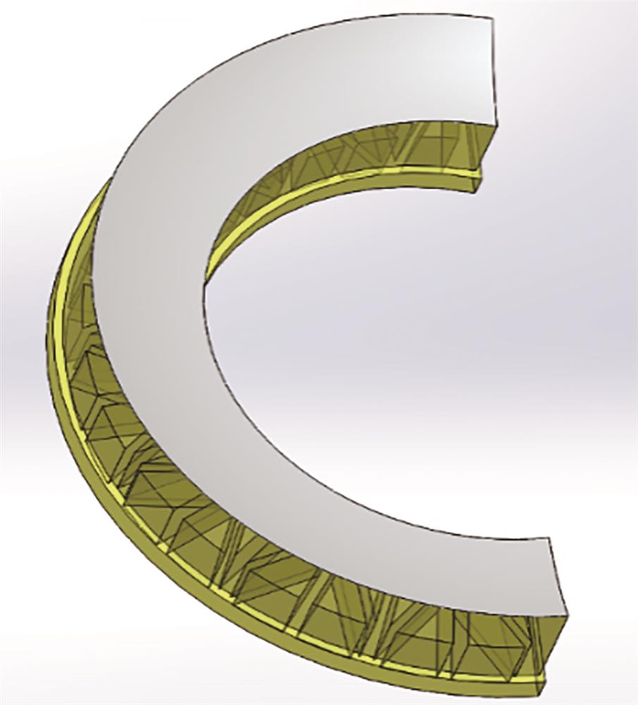
    Fig. 1. Three-dimensional diagram of the aspheric surface in higher order
    Schematic diagram of compensation detection optical path
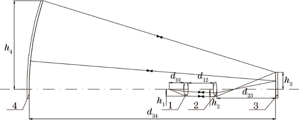
    Fig. 2. Schematic diagram of compensation detection optical path
    Optical path diagram of compensation detection system
    Fig. 3. Optical path diagram of compensation detection system
    Wavefront diagram
    Fig. 4. Wavefront diagram
    Spot diagram
    Fig. 5. Spot diagram
    Specific parameters of triangular lightweight
    Fig. 6. Specific parameters of triangular lightweight
    Three-dimensional diagram of support structure
    Fig. 7. Three-dimensional diagram of support structure
    Deformation cloud maps. (a) Deformation cloud map before lightweight; (b) deformation cloud map after lightweight
    Fig. 8. Deformation cloud maps. (a) Deformation cloud map before lightweight; (b) deformation cloud map after lightweight
    Stress cloud maps of the aspherical mirror. (a) Frontal stress cloud map; (b) rear stress cloud map
    Fig. 9. Stress cloud maps of the aspherical mirror. (a) Frontal stress cloud map; (b) rear stress cloud map
    Three-dimensional diagram of assembly structure
    Fig. 10. Three-dimensional diagram of assembly structure
    Deformation cloud maps of the mirror along the optical axis. (a) Optical axis is parallel to the direction of gravity; (b) optical axis is perpendicular to the direction of gravity
    Fig. 11. Deformation cloud maps of the mirror along the optical axis. (a) Optical axis is parallel to the direction of gravity; (b) optical axis is perpendicular to the direction of gravity
    Stress cloud maps. (a) Stress cloud map of aspherical mirror; (b) stress cloud map of supporting structure
    Fig. 12. Stress cloud maps. (a) Stress cloud map of aspherical mirror; (b) stress cloud map of supporting structure
    SurfaceRadius /mmThickness /mmGlassSemi-diameter /mmConic
    OBJInfinity222.242Air00
    198.10920.000H-K9L550
    2-570.275134.353Air550
    366.02120.000H-K9L450
    4276.057206.033Air450
    5-1200.000-1217.880Mirror450
    STO1280.9401217.880Mirror400See parameters
    7-1200.000-206.033Mirror450
    8276.057-20.000H-K9L450
    966.021-134.353Air450
    10570.275-20.000H-K9L550
    1198.109-222.242Air550
    IMAInfinity-Air7.285E-0030
    Table 1. Compensate test system structure parameters
    CompensatorRefractive indexDecenter /mmTilt /(°)Thickness /mmRadius /mmSurface irregularity /λ
    Compensator 10.0005±0.01±0.001±0.02±0.10.1
    Compensator 20.0005±0.01±0.001±0.02±0.10.1
    Compensator 3--±0.001-±0.10.2
    Table 2. Surface tolerance parameters
    Jinlong Cui, Mingyong Hu, Yachao Bi, Zhiwei Feng, Qian Bai, Guangyu Chen, Jianfeng Xu. Detection and Lightweight Analysis of Large-Diameter Semi-Annular High-Order Aspheric Surface[J]. Laser & Optoelectronics Progress, 2023, 60(7): 0722003
    Download Citation