Author Affiliations
School of Physics & State Key Laboratory of Optoelectronic Materials and Technologies, Sun Yat-sen University, Guangzhou 510275, Chinashow less
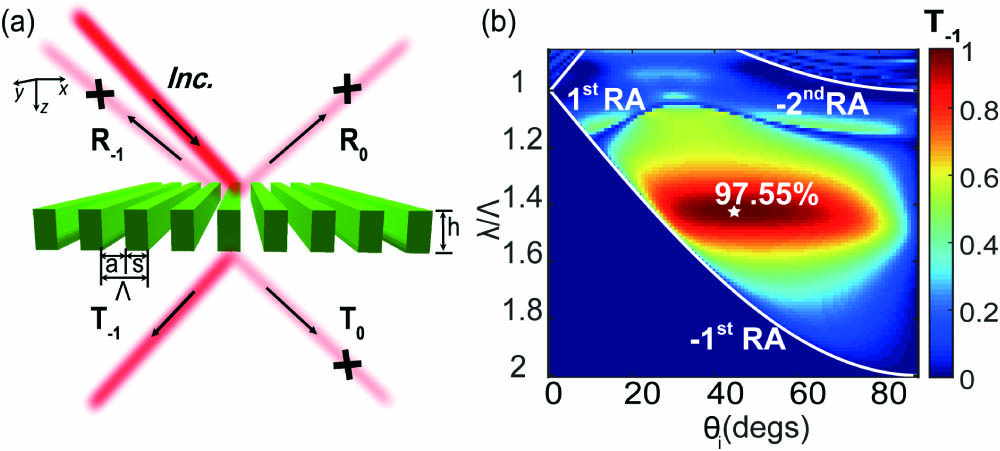
Fig. 1. Rectangular dielectric metagrating for nearly unity anomalous diffraction. (a) A schematic illustration of the dielectric metagrating with a periodicity of , composed of an array of rectangular bars with the width of and height of . (b) A phase map of the diffraction efficiency of the order, by varying the incident angle and the normalized wavelength . The metagrating parameters are and . The three white curves correspond to the , , and Rayleigh anomaly, respectively. The white star in the center marks the highest order efficiency of 97.55%.
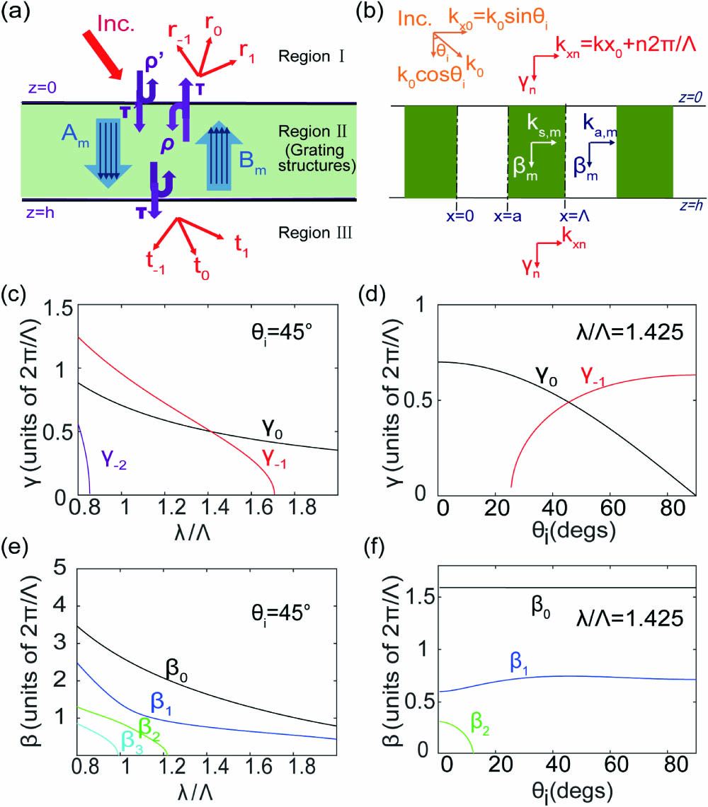
Fig. 2. Mode dispersions of the rectangular dielectric metagrating. (a) A sketch of the mode expansion and coupling mechanism of the metagrating. (b) Wavevector components of the diffraction orders or waveguide-array-modes. Here, is the z-orientation wave vector of the incidence/exit ambient (regions I and III). (c) diagram of the metagrating at . (d) diagram at , showing the appearance of the order just when . (e) diagram at . (f) diagram at . For (c)–(f), the grating parameters are and .
Fig. 3. Interferences of the modes and their contributions to the diffraction efficiencies with an incident angle of . (a) The diffraction efficiency of the order calculated by the FEM (the square marks), the waveguide-array-mode expansion method considering enough modes (solid lines), and considering two propagating modes (dashed lines). (b) The amplitudes and phase differences of the two modes versus the normalized wavelength. The superposition of these two modes’ contribution results is shown with the dashed line in (a). (c) and (d): similar to (a) and (b), but for the order. The inset in (c) shows the zoomed-in view of the diagram. The vertical dashed line indicates the normalized wavelength of 1.425.
Fig. 4. Interferences of the modes and their contributions to the diffraction efficiencies with . (a) The diffraction efficiencies versus incident angle calculated by the FEM (square marks) and the waveguide-array-mode expansion method considering enough modes (solid lines) and two propagating modes (dashed lines). The inset is the zoomed-in view of the diagram. (b) The amplitudes and phase differences of two modes at different incident angles. The two vertical dashed lines indicate the incident angles of 31° and 64°. (c) and (d): similar to (a) and (b), but for the order.
Fig. 5. Analysis of the anomalous refraction by mode decomposition. (a) The simulation result of the field obtained by the FEM in the case of and . (b) The field calculated by the waveguide-array-mode expansion method. (c) and (e) The fields of different diffraction orders in the reflected and transmitted regions, respectively. (d) The waveguide-array-modes inside the grating.
Fig. 6. Influence of material loss, material dispersion, and the substrate on the performance of the metagrating. (a) and (b) The order’s diffraction efficiency versus (a) wavelength or (b) incident angle when the dielectric bars’ extinction coefficient (red), (green dashed), and (blue). (c) The order’s diffraction efficiency versus wavelength when the dielectric bars are made of silicon-based material (green) or no-loss material with and (red). (d) The order’s diffraction efficiency versus incident angle when the dielectric bars are made of material with at the wavelength of 640 nm (red) and silicon-based material at the wavelengths of 640 nm (purple) and 653 nm (green dashed). (e) and (f) The order’s diffraction efficiency versus (e) wavelength or (f) incident angle when the metagrating is freestanding (green) or standing on the substrate (orange).