Abstract
In this Letter, we propose a metagrating consisting of simple rectangular bars for nearly unity anomalous diffraction with a large deflection angle. The analysis performed by the scattering-matrix method shows that such exceptional beam steering derives from the couplings of the two lowest propagation waveguide-array-modes and their constructive interferences. The tolerance of the incident angle for a high diffraction efficiency (e.g., >90%) is within a range of 33°. We also discuss that such an advantage still exists after considering a reasonable loss and dispersion. We envision that the proposed strategy may have wide use in the field of high-performance wavefront-shaping applications.Beam manipulation is important in a broad range of optical applications. Refractive optics has been the earliest way to realize beam manipulation by utilizing phase accumulation through bulky optical components. After that, diffraction optical elements attracted much attention due to the substantial decrease of thickness and the ability for more diversiform designs. Diffraction gratings, the periodic type of diffractive components, have been widely used in optical devices such as spectrometers and couplers. Control of diffraction orders promotes the development of various gratings, among which the blazed grating has a high performance for steering most of the incident beams into a specific order. However, it is still challenged by the shadow effect[1,2] and has a diffraction efficiency limit when operating at the large deflection angle.
Metasurfaces, a kind of artificially constructed planar component, broaden the range of possibilities for beam manipulation[3–5]. By elaborate design of the configuration of the subwavelength meta-atoms one can obtain arbitrary phase profiles, leading to the prominent functionalities such as lenses[6,7], holograms[8], beam splitters[9], and beam deflectors[10–12]. For the cases of beam deflecting or steering, metasurfaces consisting of periodically arranged supercells with a linear phase gradient distribution are severed as a blazed metagrating[13], but still suffer from the low efficiency of large-angle beam steering due to the gradient phase principle and fabrication limitations on spatial resolution. To solve the efficiency issue, some efforts have been made such as engineering the configurations to compensate the impedance mismatch[14,15], or using optimization methods[16].
Recently, the metagrating (composed of periodic arrays of meta-atoms) has been proposed. It is theoretically demonstrated that the metagrating, formed by periodic arrays of carefully tailored bianisotropic inclusions, enables ultra-high-efficiency wavefront steering through diffraction control[17]. In the regime of infrared and visible light, dielectric metagratings for high-efficiency diffraction controlling are designed using bianisotropic antennas[18], asymmetric scattering patterns[19–21], or topologically optimized structures[22–24]. But these metagratings are too complicated with extreme parameters for fabrication, which may hinder its wide application as well. In addition, it has also been demonstrated that beam steering can be realized by an array of simple cylinders[25], but again the diffraction efficiency is a little bit low. Metallic metagratings can also achieve high-efficiency beam steering by tuning the plasmonic resonance in the extraordinary optical diffraction regime[26,27], but they may suffer from intrinsic ohmic metallic loss.
In this Letter, we show that a metagrating composed of simple rectangular bars can achieve high-efficiency and large-angle deflection, with the highest efficiency reaching 97.55%. To explain this phenomenon, the waveguide-array-mode expansion method is utilized to analyze the modes in the metagrating and their coupling with the diffraction waves. We find that it arises from the constructive interference between the two lowest waveguide-array-mode’s contributions. Moreover, the diffraction efficiency of the metagrating can maintain over 90% when the incident angle ranges from 31° to 64°. Finally, we take the extinction coefficients and dispersion of the material into consideration to study the applicability of the proposed metagrating. Our work paves the way to experimentally realize high-performance wavefront shaping with a simple metagrating, which may enable the design of high-performance optical devices, such as beam scanning, spectrometry, and holography.
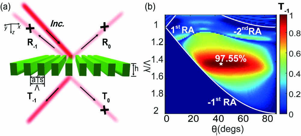
Figure 1(a) illustrates the metagrating constructed by an array of simple rectangular bars with a width of s and a height of . The refractive index of the dielectric bar is 3.0 and the periodicity of the metagrating is . and represent the reflected orders and transmitted orders, respectively. In order to achieve high-efficiency anomalous refraction with the metagrating, our strategy is to suppress all the diffraction orders except for the order. Here, the incident beam is p-polarized with the magnetic field along the y direction.

Figure 1.Rectangular dielectric metagrating for nearly unity anomalous diffraction. (a) A schematic illustration of the dielectric metagrating with a periodicity of , composed of an array of rectangular bars with the width of and height of . (b) A phase map of the diffraction efficiency of the order, by varying the incident angle and the normalized wavelength . The metagrating parameters are and . The three white curves correspond to the , , and Rayleigh anomaly, respectively. The white star in the center marks the highest order efficiency of 97.55%.
Figure 1(b) shows the order diffraction efficiency of the metagrating in a two-parameter diagram of the normalized wavelength and the incident angle. The definition of the diffraction efficiency is the energy flux of the specific order divided by the total incident energy flux. To identify the allowed propagation diffraction order, Rayleigh anomaly (RA) lines[28] are plotted in Fig. 1(b) with white curves. The th diffraction order is allowed to propagate only in the region above the th RA line. It can be found that there are just the 0th and diffraction orders in the transmission ambient within the middle panel of Fig. 1(b), which is bounded by the , , and Rayleigh anomaly curves. It is interesting that the order diffraction efficiency reaches 97.55% at the point of and , indicating nearly unity energy concentration to the order. Moreover, it maintains over 90% for the incident angle range of 31° to 64°, showing a high performance of wide-angle tolerance.
Next, we analyze the modes in the metagrating using the waveguide-array-mode expansion method[29,30] and the coupling between the waveguide-array-modes and the diffraction orders to explain the high-efficiency anomalous refraction phenomenon highlighted by the white star in Fig. 1(b), as well as the performance of wide-angle tolerance. A three-layer model for describing the mode expansion and coupling mechanism of the metagrating is shown in Fig. 2(a). Regions I and III are the reflected and transmitted ambient, and region II is the layer of grating structure. The electromagnetic fields in region I and region III can be expanded as plane waves in the directions of the incident wave and the diffraction orders, denoted by the red arrows. Inside region II, the grating bars are considered as a waveguide array[29,31,32]. The electromagnetic fields in this layer can be expanded by the sum of the waveguide-array-modes. Figure 2(b) shows the wave vector components in each region. Considering an obliquely incident beam with an incident angle and a wavenumber in vacuum, the x-orientation wave vector of the th diffraction order can be calculated by the relation (). Then, the corresponding z-orientation wave vector can be expressed by . According the above relations, the dispersion of versus the normalized wavelength can be obtained [Fig. 2(c)] when the incident angle . From Fig. 2(c), one can know that there are only 0th and diffraction orders in region I and region III in the normalized wavelength range from 0.85 to 1.70. We also plot the diagram [Fig. 2(d)] to analyze the angle tolerance of the high-efficiency anomalous refraction when the normalized wavelength . From Fig. 2(d), one can also know that there are only 0th and diffraction orders in region I and region III when the incident angle is larger than 25.2°.
Figure 2.Mode dispersions of the rectangular dielectric metagrating. (a) A sketch of the mode expansion and coupling mechanism of the metagrating. (b) Wavevector components of the diffraction orders or waveguide-array-modes. Here, is the z-orientation wave vector of the incidence/exit ambient (regions I and III). (c) diagram of the metagrating at . (d) diagram at , showing the appearance of the order just when . (e) diagram at . (f) diagram at . For (c)–(f), the grating parameters are and .
In region II, waveguide-array-modes propagate along the z direction with the propagation constants , as illustrated in Fig. 2(b). and are the x-orientation wave vectors in the dielectric bars and the air gaps, respectively. Because the metagrating consists of simple rectangular bars, one can use the analytical expressions of the waveguide-array-modes to derive the dispersion relation. By matching the continuous boundary condition and the Bloch boundary condition, one can derive the equation between and , which is expressed as[30]
Note that , , and have the following relation:
According to Eq. (1) and Eq. (2), one can get the relation between and the normalized wavelength when the incident angle [Fig. 2(e)]. From Fig. 2(e), one can know that only the 0th and 1st propagating waveguide-array-modes can be excited in region II when the normalized wavelength is larger than 1.22, while the higher-order waveguide-array-modes are evanescent waves in the grating. We can also have the relation between and the incident angle when the normalized wavelength [Fig. 2(f)]. From Fig. 2(f), one can also know that only the 0th and 1st propagating waveguide-array-modes can be excited in region II when the incident angle is larger than 12.5°.
Until now, we have known the dispersions of the excited waveguide-array-mode of the metagrating, and the allowed propagation diffraction order in an ambient medium. Next, we will investigate how the waveguide-array-modes couple to the diffraction wave, which determines the energy distribution of each diffraction order. Actually, a quantified analysis of the mode coupling process has been presented in the system of high-contrast-gratings to explain the phenomenon of broadband high reflectivity, where only the 0th diffraction order is allowed to propagate[30]. Here, we will apply this method to analyze the grating with more than one diffraction orders. We denote the reflection and transmission coefficients of the th diffraction orders as and , respectively. The waveguide-array-modes propagating forward and backward along the z direction are defined as and . They can also be expressed as the vector forms: , , , and . The vector form of the incident wave is defined as . According to the boundary condition, the scattering matrix at the interface of can be expressed as
Similarly, the scattering matrix at the interface of is
Here, the matrices , , , and describe the cross coupling between the waveguide-array-modes and their interaction with the waves in vacuum. As shown in Fig. 2(a), a part of the incident beam is directly reflected to region I with the coefficient . Meanwhile, the rest of the incident beam transmits to the grating structure with the coefficient and excites the forward propagating waveguide-array-modes . After reaching the lower interface, a part of these modes will contribute to the diffraction waves with the coefficient and the rest of them will couple to the backward propagating waveguide-array-modes with the coefficient , which is the same for the upper interface when the backward propagating modes reach.
From Eq. (4), one can know the transmission coefficients can be expressed as
The diffraction efficiency of each transmission order is expressed as
Note that the highest efficiency in Fig. 1(b) corresponds to the case of and . Figure 3 shows the spectra in the normalized wavelength range from 1.22 to 1.69 of the diffraction efficiencies of and orders when the incident angle . In this range, one can find that there are just 0th and −1st diffraction orders from Fig. 2(c) and the two lowest waveguide-array-modes ( and ) will propagate from Fig. 2(e). The solid lines in Figs. 3(a) and 3(c) are the results calculated by Eq. (5) and Eq. (6) with enough waveguide-array-modes considered. It agrees well with the simulation result obtained by the finite element method (FEM), which is shown by the square marks. This indicates that our method based on the waveguide-array-mode expansion is correct. The dashed lines are the results calculated by Eq. (5) and Eq. (6) but considering only the two lowest waveguide-array-modes. They are approximate to the simulation and the enough modes calculation as well, which implies that the main contributions for the diffraction orders are from the propagating waveguide-array-modes.
Figure 3.Interferences of the modes and their contributions to the diffraction efficiencies with an incident angle of . (a) The diffraction efficiency of the order calculated by the FEM (the square marks), the waveguide-array-mode expansion method considering enough modes (solid lines), and considering two propagating modes (dashed lines). (b) The amplitudes and phase differences of the two modes versus the normalized wavelength. The superposition of these two modes’ contribution results is shown with the dashed line in (a). (c) and (d): similar to (a) and (b), but for the order. The inset in (c) shows the zoomed-in view of the diagram. The vertical dashed line indicates the normalized wavelength of 1.425.
To understand the mechanism of the high-efficiency anomalous refraction in detail, the individual contributions of the first two waveguide-array-modes (mode0 and mode1) are calculated. According to Eq. (5), the transmission coefficient of each diffraction order is the coherent superposition of each waveguide-array-mode’s contribution, i.e.,
In Eq. (7) [Eq. (8)], the first term is mode0’s contribution and the second term is mode1’s contribution for the () order. Figure 3(b) shows the amplitudes of mode0’s contribution (black solid line) and mode1’s contribution (black dashed line). The blue line represents the phase difference between mode0’s contribution and mode1’s contribution. Note that these two amplitudes are nearly equal and the phase difference is near zero when the normalized wavelength . The diffraction efficiency resulting from the constructive interference of these two modes is shown by the dashed line in Fig. 3(a) and the result at is near 100%, which is consist with the result calculated by the FEM. Therefore, it is the constructive interference between mode0’s contribution and mode1’s contribution that results in the high-efficiency anomalous refraction at . In Fig. 3(a), away from the point of , the dashed line is close to the solid line in the long-wavelength region but deviates from the solid line in the short-wavelength region. This small discrepancy indicates that the two lowest propagating modes play a major role in generating the diffraction waves and the other evanescent modes also have contribution in the short-wavelength region. In the same way, we also calculate the diffraction efficiency of the order. In Fig. 3(c), the vertical dashed line also indicates the normalized wavelength of 1.425 and the inset shows the zoomed-in view of the diagram. One can see that the diffraction efficiency of the order at is near zero. Similarly, we also calculate the amplitudes of mode0’s contribution (black solid line) and mode1’s contribution (black dashed line), as shown in Fig. 3(d). The blue line represents the phase difference between mode0’s contribution and mode1’s contribution. Note that these two amplitudes are nearly equal at , but the phase difference is near . Thus, the destructive interference between these two modes’ contributions leads to the ultra-low diffraction efficiency of the order at . Compared with the dashed line in Fig. 3(c), the discrepancy between the dashed line and the solid line in the short-wavelength region is larger in Fig. 3(a). Because the evanescent modes provide more contribution to the order in the short-wavelength region.
Next, we will explain the wide-angle tolerance phenomenon of the high-efficiency anomalous refraction. Here, we set the normalized wavelength equal to 1.425 and calculate the diffraction efficiency of the and orders when the incident angle changes from 20° to 80°. As shown in Fig. 4(a), the result calculated by Eq. (5) and Eq. (6) with enough waveguide-array-modes considered (solid line) agrees well with the simulation result obtained by the FEM (square mark). The inset shows the zoomed-in view of the diagram. In the small-angle region, the diffraction efficiency of the order is zero. This is because the order is not allowed to propagate in this region, according to the result shown in Fig. 2(d). One can see that the diffraction efficiency of the order maintains over 90% when the incident angle ranges from 31° to 64°. To explain this phenomenon, we calculate the individual contribution of the first two waveguide-array-modes [Fig. 4(b)]. Figure 4(b) shows the amplitudes of mode0’s contribution (black solid line) and mode1’s contribution (black dashed line). The blue line represents the phase difference between these two modes’ contributions. When the incident angle ranges from 31° to 64°, one can see that the amplitudes of these two modes’ contributions are nearly equal and the phase difference stays close to zero. The diffraction efficiency resulting from the constructive interference of these two modes is shown by the dashed line in Fig. 4(a), which is consist with the result calculated by the FEM. Therefore, it is the constructive interference between these two modes’ contributions over a wide angle range that results in the wide-angle tolerance of the high-efficiency anomalous refraction. In contrast, the diffraction efficiency of the order is near zero when the incident angle ranges from 31° to 64° [Fig. 4(c)]. From the amplitudes and phase differences of two modes’ contributions [Fig. 4(d)], one can find that it is the destructive interference between these two modes’ contributions over a wide angle range that results in the near-zero diffraction efficiency, as shown by the dashed line in Fig. 4(d).
Figure 4.Interferences of the modes and their contributions to the diffraction efficiencies with . (a) The diffraction efficiencies versus incident angle calculated by the FEM (square marks) and the waveguide-array-mode expansion method considering enough modes (solid lines) and two propagating modes (dashed lines). The inset is the zoomed-in view of the diagram. (b) The amplitudes and phase differences of two modes at different incident angles. The two vertical dashed lines indicate the incident angles of 31° and 64°. (c) and (d): similar to (a) and (b), but for the order.
Apart from the diffraction efficiency, we also calculate the electric fields in each region. We calculate the field distribution when and , by both the FEM full wave simulation [Fig. 5(a)] and the waveguide-array-mode expansion method [Fig. 5(b)]. They are quite consistent with each other. By decomposing the total field into a series of the waveguide-array-modes, one can see that just the two lowest propagating modes are excited while the second-order () evanescent mode is excited a little bit in Fig. 5(d), which is consistent with the result in Fig. 2(e). In addition, one can also decompose the total field in region I and region III, as shown in Figs. 5(c) and 5(e). It is obviously that nearly all the electromagnetic waves are deflected to the order, which is consistent with the results shown in Figs. 3(a) and 4(a).
Figure 5.Analysis of the anomalous refraction by mode decomposition. (a) The simulation result of the field obtained by the FEM in the case of and . (b) The field calculated by the waveguide-array-mode expansion method. (c) and (e) The fields of different diffraction orders in the reflected and transmitted regions, respectively. (d) The waveguide-array-modes inside the grating.
In practice, the loss and dispersion of the material should be considered. Now, we study the influence of material loss and dispersion on the performance of the metagrating. We first study the influence of the material loss by considering the metagrating whose dielectric bars are made of material with a fixed refraction index () but different extinction coefficients . Figure 6(a) shows that the diffraction efficiency with a small extinction coefficient (, green dashed) is nearly the same as in the no-loss case (, red), and it will still keep a high level with the value of 93.29% when (blue). Similar behavior is found out when changing the incident angle at the normalized wavelength of 1.425. From Fig. 6(b), one can see that the spectrum in the case of is nearly the same as in the case of . When , the high-efficiency (over 90%) range changes to , which is still a large wide-angle tolerance. Note that the value of the extinction coefficient discussed above is the representative number for common dielectric materials such as silicon and silicon nitride.
Figure 6.Influence of material loss, material dispersion, and the substrate on the performance of the metagrating. (a) and (b) The order’s diffraction efficiency versus (a) wavelength or (b) incident angle when the dielectric bars’ extinction coefficient (red), (green dashed), and (blue). (c) The order’s diffraction efficiency versus wavelength when the dielectric bars are made of silicon-based material (green) or no-loss material with and (red). (d) The order’s diffraction efficiency versus incident angle when the dielectric bars are made of material with at the wavelength of 640 nm (red) and silicon-based material at the wavelengths of 640 nm (purple) and 653 nm (green dashed). (e) and (f) The order’s diffraction efficiency versus (e) wavelength or (f) incident angle when the metagrating is freestanding (green) or standing on the substrate (orange).
We then study the performance of the metagrating made of a realistic lossy silicon-based material, with both the loss and dispersion considered. The refractive index and extinction coefficient are shown in the inset of Fig. 6(c). Here, we consider the metagrating with , , and periodicity . In this case, the peak position of the metagrating with is 640 nm, according to the results in Fig. 3(a). Figure 6(c) shows the order’s diffraction efficiency versus wavelength when the dielectric bars are made of either the lossy material (green) or the no-loss material with (red). The efficiency of the lossy case drops a little and the low-quality peak also shifts. Figure 6(d) shows the efficiency of the lossy case still has a wide enough angle tolerance at both wavelengths of 640 nm and 653 nm.
We also study the influence of the substrate on the performance of the metagrating. Figure 6(e) shows the order’s diffraction efficiency versus wavelength when the metagrating is freestanding (green) or standing on the substrate (orange). One can see that the peak efficiency only drops a little when the substrate is considered. Figure 6(f) shows the diffraction efficiency of the metagrating with the substrate has still wide enough angle tolerance at the peak wavelength of 653 nm. In addition, one may further broaden the bandwidth by using a low waveguide-array-mode dispersion. For example, a straightforward way is to use a lower refraction index material for the metagrating design.
In summary, we demonstrate that a metagrating composed of an array of rectangular bars can achieve a high efficiency (the highest efficiency reaches 97.55%) and large-angle deflection without the requirement of a complex structure. Furthermore, the diffraction efficiency stays over 90% when the incident angle ranges from 31° to 64°. The property of wide incident angle tolerance, which is desirable in many applications, may enable the design of angle-insensitive and high-efficiency optical devices. Using the waveguide-array-mode expansion method, we find that it is the constructive interference between the waveguide-array-modes’ contributions over a wide angle range that results in the high-efficiency and wide-angle anomalous refraction. This indicates that control of each waveguide-array-mode’s contribution in the metagrating may be a feasible way to design high-performance optical devices. By considering the extinction loss and dispersion of a realistic silicon-based material, or different material loss coefficients, we expect that a silicon-based metagrating can be used to achieve large angle deflection with a high efficiency.
References
[1] T. Hessler, M. Rossi, R. E. Kunz, M. T. Gale. Appl. Opt., 37, 4069(1998).
[2] P. Lalanne, S. Astilean, P. Chavel, E. Cambril, H. Launois. J. Opt. Soc. Am. A, 16, 1143(1999).
[3] N. Yu, P. Genevet, M. A. Kats, F. Aieta, J.-P. Tetienne, F. Capasso, Z. Gaburro. Science, 334, 333(2011).
[4] P. Genevet, F. Capasso, F. Aieta, M. Khorasaninejad, R. Devlin. Optica, 4, 139(2017).
[5] S. Sun, Q. He, J. Hao, S. Xiao, L. Zhou. Adv. Opt. Photonics, 11, 380(2019).
[6] M. Khorasaninejad, F. Capasso. Science, 358, eaam8100(2017).
[7] Z.-B. Fan, Z.-K. Shao, M.-Y. Xie, X.-N. Pang, W.-S. Ruan, F.-L. Zhao, Y.-J. Chen, S.-Y. Yu, J.-W. Dong. Phys. Rev. Appl., 10, 014005(2018).
[8] W. Wan, J. Gao, X. Yang. Adv. Opt. Mater., 5, 1700541(2017).
[9] X. Zhang, R. Deng, F. Yang, C. Jiang, S. Xu, M. Li. ACS Photonics, 5, 2997(2018).
[10] S. Sun, K.-Y. Yang, C.-M. Wang, T.-K. Juan, W. T. Chen, C. Y. Liao, Q. He, S. Xiao, W.-T. Kung, G.-Y. Guo. Nano Lett., 12, 6223(2012).
[11] Y. F. Yu, A. Y. Zhu, R. Paniagua-Domínguez, Y. H. Fu, B. Luk’yanchuk, A. I. Kuznetsov. Laser Photonics Rev., 9, 412(2015).
[12] Z. Zhou, J. Li, R. Su, B. Yao, H. Fang, K. Li, L. Zhou, J. Liu, D. Stellinga, C. P. Reardon. ACS Photonics, 4, 544(2017).
[13] D. Lin, P. Fan, E. Hasman, M. L. Brongersma. Science, 345, 298(2014).
[14] A. Díaz-Rubio, V. S. Asadchy, A. Elsakka, S. A. Tretyakov. Sci. Adv., 3, e1602714(2017).
[15] V. S. Asadchy, A. Wickberg, A. Díaz-Rubio, M. Wegener. ACS Photonics, 4, 1264(2017).
[16] Z. Lin, B. Groever, F. Capasso, A. W. Rodriguez, M. Lončar. Phys. Rev. Appl., 9, 044030(2018).
[17] Y. Ra’di, D. L. Sounas, A. Alù. Phys. Rev. Lett., 119, 067404(2017).
[18] Z. Fan, M. R. Shcherbakov, M. Allen, J. Allen, B. Wenner, G. Shvets. ACS Photonics, 5, 4303(2018).
[19] E. Khaidarov, H. Hao, R. Paniagua-Domínguez, Y. F. Yu, Y. H. Fu, V. Valuckas, S. L. K. Yap, Y. T. Toh, J. S. K. Ng, A. I. Kuznetsov. Nano Lett., 17, 6267(2017).
[20] R. Paniagua-Dominguez, Y. F. Yu, E. Khaidarov, S. Choi, V. Leong, R. M. Bakker, X. Liang, Y. H. Fu, V. Valuckas, L. A. Krivitsky. Nano Lett., 18, 2124(2018).
[21] T. Shi, Y. Wang, Z. L. Deng, X. Ye, Z. Dai, Y. Cao, B. O. Guan, S. Xiao, X. Li. Adv. Opt. Mater., 7, 1901389(2019).
[22] D. Sell, J. Yang, S. Doshay, R. Yang, J. A. Fan. Nano Lett., 17, 3752(2017).
[23] D. Sell, J. Yang, E. W. Wang, T. Phan, S. Doshay, J. A. Fan. ACS Photonics, 5, 2402(2018).
[24] J. Yang, D. Sell, J. A. Fan. Ann. Phys., 530, 1700302(2018).
[25] W. Liu, A. E. Miroshnichenko. ACS Photonics, 5, 1733(2017).
[26] Z.-L. Deng, S. Zhang, G. P. Wang. Nanoscale, 8, 1588(2016).
[27] Z.-L. Deng, J. Deng, X. Zhuang, S. Wang, T. Shi, G. P. Wang, Y. Wang, J. Xu, Y. Cao, X. Wang. Light: Sci. Appl., 7, 78(2018).
[28] A. A. Maradudin, I. Simonsen, J. Polanco, R. M. Fitzgerald. J. Opt., 18, 024004(2016).
[29] V. Karagodsky, F. G. Sedgwick, C. J. Chang-Hasnain. Opt. Express, 18, 16973(2010).
[30] C. J. Chang-Hasnain, W. Yang. Adv. Opt. Photonics, 4, 379(2012).
[31] Z. Wang, B. Zhang, H. Deng. Phys. Rev. Lett., 114, 073601(2015).
[32] W. Liu, T. Yu, Y. Sun, Z. Lai, Q. Liao, T. Wang, L. Yu, H. Chen. Phys. Rev. Appl., 11, 064005(2019).