• Laser & Optoelectronics Progress
  • Vol. 58, Issue 24, 2400001 (2021)
Yanqing Shi, Caixia Chang, Xiaohong Liu, Ziyu Li, Zonghua Zhang*, Nan Gao, and Zhaozong Meng
Author Affiliations
  • School of Mechanical Engineering, Hebei University of Technology, Tianjin 300130, China
  • show less
    DOI: 10.3788/LOP202158.2400001 Cite this Article Set citation alerts
    Yanqing Shi, Caixia Chang, Xiaohong Liu, Ziyu Li, Zonghua Zhang, Nan Gao, Zhaozong Meng. Calibration Methods and Progress for Internal and External Parameters of Area-Array Camera[J]. Laser & Optoelectronics Progress, 2021, 58(24): 2400001 Copy Citation Text show less
    Imaging model of pinhole camera[23]
    Fig. 1. Imaging model of pinhole camera[23]
    Lens distortion
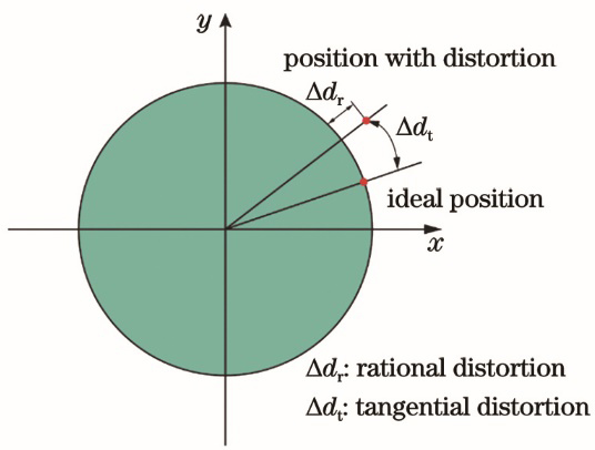
    Fig. 2. Lens distortion
    Plane calibration boards. (a) Checkerboard; (b) solid circle; (c) concentric ring; (d) phase target
    Fig. 3. Plane calibration boards. (a) Checkerboard; (b) solid circle; (c) concentric ring; (d) phase target
    Radial distortion of lens
    Fig. 4. Radial distortion of lens
    Partial processes of chessboard calibration method. (a) Checkerboard patterns captured by camera under different poses; (b) corners of calibration image
    Fig. 5. Partial processes of chessboard calibration method. (a) Checkerboard patterns captured by camera under different poses; (b) corners of calibration image
    Double parallel plane model
    Fig. 6. Double parallel plane model
    Schematic of perspective protection of spatial circle[31]
    Fig. 7. Schematic of perspective protection of spatial circle[31]
    Perspective projection transformation of spatial concentric circle[33]. (a) Concentric circle in object plane; (b) concentric circle in imaging plane
    Fig. 8. Perspective projection transformation of spatial concentric circle[33]. (a) Concentric circle in object plane; (b) concentric circle in imaging plane
    Principle diagram of line-edge segmentation[40]. (a) Principle of segmentation; (b) result of segmentation
    Fig. 9. Principle diagram of line-edge segmentation[40]. (a) Principle of segmentation; (b) result of segmentation
    Iterative calibration process of circular feature points on target[46]
    Fig. 10. Iterative calibration process of circular feature points on target[46]
    Phase target patterns. (a) Horizontal sinusoidal fringe; (b) vertical sinusoidal fringe; (c) phase target determined by horizontal and vertical sinusoidal fringes
    Fig. 11. Phase target patterns. (a) Horizontal sinusoidal fringe; (b) vertical sinusoidal fringe; (c) phase target determined by horizontal and vertical sinusoidal fringes
    Mapping relationship between world coordinates of phase points and camera pixel coordinates[55]
    Fig. 12. Mapping relationship between world coordinates of phase points and camera pixel coordinates[55]
    New applications of camera technology. (a) Optical system and opto-mechanical image of spatial fisheye camera[94]; (b) 3D shape measurement of specular objects based on bi-telecentric lens camera[95]; (c) application and calibration of underwater camera[96]; (d) application and calibration of defocus camera[97]
    Fig. 13. New applications of camera technology. (a) Optical system and opto-mechanical image of spatial fisheye camera[94]; (b) 3D shape measurement of specular objects based on bi-telecentric lens camera[95]; (c) application and calibration of underwater camera[96]; (d) application and calibration of defocus camera[97]
    Checkerboard images before and after calibration [103]. (a) Distorted; (b) corrected
    Fig. 14. Checkerboard images before and after calibration [103]. (a) Distorted; (b) corrected
    Self-calibration method in Ref. [104]
    Fig. 15. Self-calibration method in Ref. [104]
    Calibration of wide-angle lens distortion[103]. (a) Diagram of experimental apparatus; (b) radial distorted phase distribution
    Fig. 16. Calibration of wide-angle lens distortion[103]. (a) Diagram of experimental apparatus; (b) radial distorted phase distribution
    Schematic of bi-telecentric camera system[106]
    Fig. 17. Schematic of bi-telecentric camera system[106]
    Calibration process of defocus camera[117]
    Fig. 18. Calibration process of defocus camera[117]
    Estimation procedures of defocus map[97]
    Fig. 19. Estimation procedures of defocus map[97]
    Calibration process of camera[116]
    Fig. 20. Calibration process of camera[116]
    MethodRef.TargetComplexitySpeedAccuracyRobustness
    Traditional calibration method[35]YesLowMediumLowLow
    [39]YesHighLowHighHigh
    [28]YesLowMediumHighHigh
    [43]YesHighLowHighHigh
    [33]YesMediumMediumHighHigh
    [55]YesLowHighHighHigh
    Self-calibration method[63]NoHighHighLowLow
    [65]NoMediumHighLowLow
    [72]NoMediumHighLowMedium
    Active-vision-based calibration method[76]NoLowHighLowMedium
    [77]YesLowHighMediumMedium
    [81]NoLowHighMediumMedium
    [82]NoLowHighMediumHigh
    Table 1. Performance comparison among different calibration methods
    Yanqing Shi, Caixia Chang, Xiaohong Liu, Ziyu Li, Zonghua Zhang, Nan Gao, Zhaozong Meng. Calibration Methods and Progress for Internal and External Parameters of Area-Array Camera[J]. Laser & Optoelectronics Progress, 2021, 58(24): 2400001
    Download Citation