• Chinese Optics Letters
  • Vol. 17, Issue 4, 041101 (2019)
Dixiang Shao1、2, Chen Yao2, Tao Zhou2, Rong Zhang2, Zhanglong Fu2, Songlin Zhuang1, and Juncheng Cao2、*
Author Affiliations
  • 1Shanghai Key Laboratory of Modern Optical System and Engineering Research Center of Optical Instrument and System, Ministry of Education, University of Shanghai for Science and Technology, Shanghai 200093, China
  • 2Key Laboratory of Terahertz Solid-State Technology, Shanghai Institute of Microsystem and Information Technology, Chinese Academy of Sciences, Shanghai 200050, China
  • show less
    DOI: 10.3788/COL201917.041101 Cite this Article Set citation alerts
    Dixiang Shao, Chen Yao, Tao Zhou, Rong Zhang, Zhanglong Fu, Songlin Zhuang, Juncheng Cao. Terahertz imaging using an optical frequency comb source[J]. Chinese Optics Letters, 2019, 17(4): 041101 Copy Citation Text show less
    Experimental configuration of the THz imaging system. LD, laser diode; PM, phase modulator; MZM, Mach–Zehnderintensity modulator; RF, radio frequency source; UTC-PD, uni-traveling photodiode; LA, locked-in amplifier; SBD, Schottky barrier diode; PC, personal computer; PM1, PM2, PM3, and PM4, parabolic mirrors.
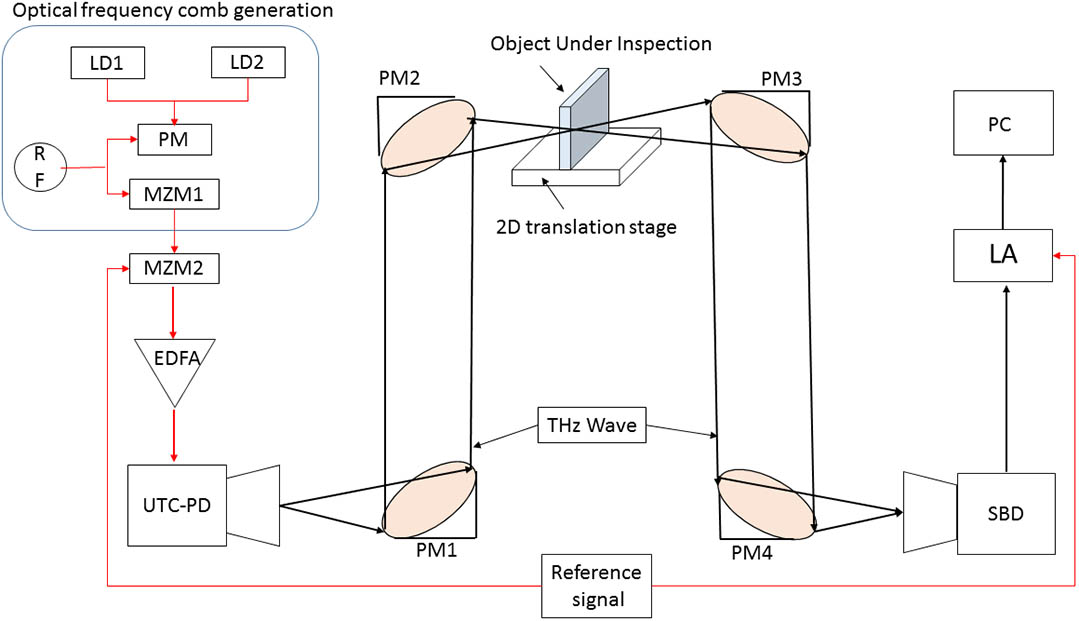
    Fig. 1. Experimental configuration of the THz imaging system. LD, laser diode; PM, phase modulator; MZM, Mach–Zehnderintensity modulator; RF, radio frequency source; UTC-PD, uni-traveling photodiode; LA, locked-in amplifier; SBD, Schottky barrier diode; PC, personal computer; PM1, PM2, PM3, and PM4, parabolic mirrors.
    Output spectra of the experimentally generated combs when (a) f∼8 GHz and DC bias voltage of ∼7.1 V is applied on the MZM. (b) f∼15 GHz and DC bias voltage of ∼8.8 V is applied on the MZM.
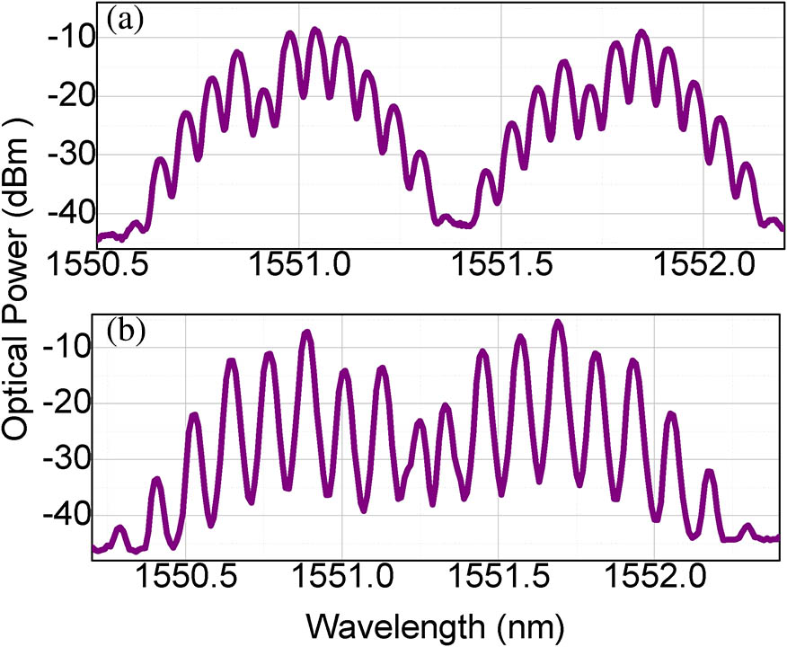
    Fig. 2. Output spectra of the experimentally generated combs when (a) f8GHz and DC bias voltage of 7.1V is applied on the MZM. (b) f15GHz and DC bias voltage of 8.8V is applied on the MZM.
    Pictures of the sample under inspection: (a) the wrench, (b) the wrench sandwiched between two thick cardboards (each ∼3 mm thick).
    Fig. 3. Pictures of the sample under inspection: (a) the wrench, (b) the wrench sandwiched between two thick cardboards (each 3mm thick).
    Images of the wrench obtained by different optical sources. (a) Monochromatic source where two wavelengths are separated by ∼100 GHz. (b) Optical frequency combs with f∼1 GHz and DC bias voltage of ∼10.4 V. (c) Optical frequency combs with f∼8 GHz and DC bias voltage of ∼7.1 V. (d) Optical frequency combs with f∼15 GHz and DC bias voltage of ∼8.8 V.
    Fig. 4. Images of the wrench obtained by different optical sources. (a) Monochromatic source where two wavelengths are separated by 100GHz. (b) Optical frequency combs with f1GHz and DC bias voltage of 10.4V. (c) Optical frequency combs with f8GHz and DC bias voltage of 7.1V. (d) Optical frequency combs with f15GHz and DC bias voltage of 8.8V.
    Dixiang Shao, Chen Yao, Tao Zhou, Rong Zhang, Zhanglong Fu, Songlin Zhuang, Juncheng Cao. Terahertz imaging using an optical frequency comb source[J]. Chinese Optics Letters, 2019, 17(4): 041101
    Download Citation