
Xuan Mao, Hong Yang, Dan Long, Min Wang, Peng-Yu Wen, Yun-Qi Hu, Bo-Yang Wang, Gui-Qin Li, Jian-Cun Gao, Gui-Lu Long, "Experimental demonstration of mode-matching and Sagnac effect in a millimeter-scale wedged resonator gyroscope," Photonics Res. 10, 2115 (2022)
- Photonics Research
- Vol. 10, Issue 9, 2115 (2022)
Abstract
1. INTRODUCTION
Chip-based devices are a mainstream of development in recent years, such as optical sensing [1], quantum key distribution [2,3], and photon sources [4]. Gyroscopes for rotation sensing with high sensitivity and precision have been studied in various systems ranging from cold atom systems [5,6] to optomechanical systems [7,8], photon and matter-wave interferometers [9,10], micro-optical-electro-mechanical systems [11,12], and solid spin systems [13–15]. Based on the Sagnac effect [16], the phase difference between two counterpropagation beams in a resonator resulting from rotation, optical gyroscopes [17–23] have been widely used in numerous applications such as remote control [24] and optical test for gravitation theories [25] in recent decades. Therefore, observation of the Sagnac effect is a crucial step to perform rotation sensing and provides the feasibility of developing a gyroscope in optical systems.
Whispering-gallery-mode (WGM) resonators as a crucial branch of optical systems have become a promising platform for both fundamental research [26–28] and practical applications [29–36] owing to the ability to enhance light–matter interaction in an ultra-small volume. Among these applications, WGM resonators play a significant role in sensing of different physical quantities such as nanoparticles [1,37,38], pressure [39], acceleration [40], and rotation velocity [41–44]. The highly efficient coupling [45–48] of light from conventional components to optical modes is a crucial factor in the development of chip-based devices. Besides, the fabrication of WGM resonators is compatible with the traditional semiconductor material processing, which promises the integration of optical gyroscopes based on WGM resonators. During the fabrication, photoresist is spin coated in the top of silicon dioxide layer, and then the pattern of the mask is transferred to photoresist after ultraviolet exposure and development. HF etching and
In this paper, we theoretically analyze and experimentally demonstrate the mode-matching between the propagation constants of the fiber taper and the WGM in resonators, which are associated with geometry dimensions. The results show that both the coupling efficiency and the
Sign up for Photonics Research TOC. Get the latest issue of Photonics Research delivered right to you!Sign up now
2. MODE-MATCHING BETWEEN WEDGED RESONATOR AND FIBER TAPER
Consider a WGM resonator with a radius of
For a fiber taper with a core radius of
In the experiments, the WGM of the resonator can be excited by a fiber taper. The intracavity power
The optical circuit used in the experiment is shown in Fig. 1. The experimental setup possesses two different functions: (i) performing
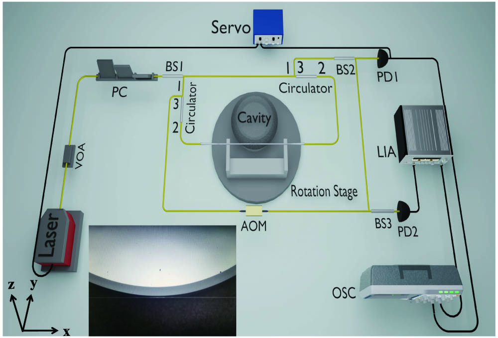
Figure 1.Optical circuit of the experiment. VOA, variable optical attenuator; PC, polarization controller; BS, beam splitter; AOM, acoustic optical modulator; PD, photodetector; OSC, oscilloscope; LIA, lock-in amplifier. The inset illustrates the top view of the coupling between the wedged resonator and the fiber taper.
To perform
Observing the mode-matching between the fiber taper and the wedged resonator, we couple the resonator with a different position along the fiber taper. The diameter distribution of the fiber taper is illustrated in Fig. 2(e), and every dot corresponds to a
![]()
Figure 2.Characterization of the fiber taper. (a)–(d) are the side view scanning electron microscope images of the fiber taper. (e) illustrates the diameters of the fiber taper versus relative distances to the marked point in the experiment along the
To demonstrate the influence of the diameter of the fiber taper on the coupling efficiency, the resonator coupling with different positions along the fiber taper and the transmission spectra exhibit different linewidths and coupling depths. Figure 3(a) shows the transmission spectra as the diameter of the fiber taper increases where the diameters are 5.81 μm, 6.60 μm, 7.17 μm, 7.63 μm, and 8.52 μm, respectively. Furthermore, the coupling efficiency and the loaded
![]()
Figure 3.Experimental results. (a) Transmission spectra of the wedged resonator coupled with different positions of the fiber taper characterized by different diameters. The inset illustrates the theoretical prediction
The diameter of the fiber taper also has significant impact on the loaded
3. SAGNAC EFFECT IN A WEDGED RESONATOR GYROSCOPE
The Sagnac effect is the basis of rotation sensing in an optical resonator. In an optical resonator of radius
The gyroscope sensing unit includes the high-
Combining the above analysis and Fig. 1, one can find the different pathways from BS1 to BS3. ① The light from BS1 and circulator transmits through fiber taper from the right hand while it does not couple into the cavity. ② The light from BS1 and circulator transmits through fiber taper from the right hand and couples into the cavity. ③ The light from BS1 and the other circulator transmits through fiber taper from the left hand while it does not couple into the cavity. ④ The light from BS1 and the other circulator transmits through the fiber taper from the left hand and couples into the cavity. Before BS3, the light of the pathways ① and ② experiences additional frequency shift
To test the resonator gyroscope, a fixed rotation frequency or direction is introduced into the system, and the experimental results are demonstrated by Fig. 4(a). The gyroscope readouts vary with the LIA reference frequency, and the highest amplitude is corresponding to the most appropriate LIA reference frequency. The insets in Fig. 4(a) illustrate the intracavity lights experiencing the Sagnac frequency shift when the resonator rotates in the CW and CCW directions. The red (blue) arrow indicates the propagating light have red (blue) frequency shift.
![]()
Figure 4.Experimental results. (a) Gyroscope readouts versus LIA reference frequency for different rotation directions. (b) Gyroscope readouts versus rotation velocity with fixed LIA reference frequency and the same rotation direction.
On the other hand, we observe the gyroscope readouts in Fig. 4(b) with a fixed LIA reference frequency, the same rotation direction, and different rotation velocities. Similar to Fig. 4(a), the amplitude tends to increase as the rotation velocity increases before a specific velocity
Combining the results of Figs. 4(a) and 4(b), we can establish a one-to-one correspondence between the LIA reference frequency and rotation velocity. Benefiting from the relatively narrow linewidth of the LIA filter, it is more accurate for us to establish the one-to-one correspondence. The best-matched reference frequency reflects the frequency beat due to the Sagnac effect in the resonator.
We investigate the gyroscope readouts for different rotation velocities and directions, and the experimental results are shown in Fig. 5. The resonator experiences rest-accelerating-uniform angular velocity-decelerating-rest five states in every experiment. From top to bottom, the rotation modes are 5 deg/s CCW, 7 deg/s CW, and 8 deg/s CCW, respectively. Using the one-to-one correspondence as mentioned above, the reference frequency is set to the best-matched value. As the frequency beat is proportional to the rotation frequency as indicated in Eq. (8), the amplitude variation behaviors are similar to the change of rotation velocity as shown in Fig. 5. The purple boxes in the figure are the data points. The red lines represent the average value of the output signal of the gyroscope in the presence of the uniform angular velocity, and the green lines represent the average value of the output signal when the gyroscope is at rest. According to the amplitude value, the optical resonator gyroscope can distinguish between static and rotating.
![]()
Figure 5.Experimental results. Gyroscope readouts when the wedged resonator experiences rest-accelerating-rotate uniformly-decelerating-rest five states for different rotation velocities and different directions. From top to bottom, the rotation modes are 5 deg/s CCW, 7 deg/s CW, and 8 deg/s CCW, respectively.
In order to accurately verify the Sagnac effect in the optical cavity, we detect the frequency beats at different speeds, and the results are shown in Fig. 6. The detected frequency beats of CW and CCW rotation directions are marked by triangles and circles, respectively. The solid line shows the theoretical curve dominated by Eq. (8). The parameter values used here are
![]()
Figure 6.Detected frequency beat versus rotation frequency. CW and CCW rotation directions are marked by triangles and circles, respectively. The solid line denotes the theoretical curve presented by Eq. (
4. CONCLUSION AND OUTLOOK
In this paper, the mode-matching between the propagation constants associated with geometry dimensions of the fiber taper and the WGM in resonator is theoretically analyzed and experimentally verified. We have demonstrated a bidirectional pump and probe scheme to directly measure the frequency beat caused by the rotation of the counterpropagating light pairs in the resonator. Benefiting from the stability of laser frequency locking and the advantages of the narrow linewidth of the LIA, we establish the linear correspondence between the detected beat frequency and the rotation velocity. On the other hand, due to introducing the asymmetry operation of the two light paths, the CW rotation and CCW rotation can be distinguished according to the value of the frequency beat. Furthermore, we implement experiments with some specific rotation velocity and two different rotation directions, and the results show that the frequency beat is proportional to the rotation frequency no matter which direction the gyroscope rotates in, which verifies that the frequency beat we observed is indeed caused by the Sagnac effect. The frequency beats we detected have good agreement with the theoretical curve. It is believed that the bigger wedged resonator and the higher quality factor promise lower detectable rotation rates. In the past decades, lots of methods emerge to reinforce the performance of gyroscopes such as the exceptional point [8,42,55,56] and exceptional surfaces [1,57,58], parity–time symmetry [59,60] and anti-parity–time symmetry [61,62], and nonlinear enhancement [61,63,64]. Combining these methods, the precision and the sensitivity of the resonator gyroscope can be further reinforced. The experimental results demonstrated in the main text verified the feasibility of developing a gyroscope in a WGM resonator system. The proposed configuration may inspire new technological developments in various schemes in which measuring low rotation rates via ultra-compact systems is highly attractive.
References
[1] G.-Q. Qin, R.-R. Xie, H. Zhang, Y.-Q. Hu, M. Wang, G.-Q. Li, H. Xu, F. Lei, D. Ruan, G.-L. Long. Experimental realization of sensitivity enhancement and suppression with exceptional surfaces. Laser Photon. Rev., 15, 2000569(2021).
[2] H. Semenenko, P. Sibson, A. Hart, M. G. Thompson, J. G. Rarity, C. Erven. Chip-based measurement-device-independent quantum key distribution. Optica, 7, 238-242(2020).
[3] F.-X. Wang, W. Wang, R. Niu, X. Wang, C.-L. Zou, C.-H. Dong, B. E. Little, S. T. Chu, H. Liu, P. Hao, S. Liu, S. Wang, Z.-Q. Yin, D.-Y. He, W. Zhang, W. Zhao, Z.-F. Han, G.-C. Guo, W. Chen. Quantum key distribution with on-chip dissipative Kerr soliton. Laser Photon. Rev., 14, 1900190(2020).
[4] M. Wang, R. Wu, J. Lin, J. Zhang, Z. Fang, Z. Chai, Y. Cheng. Chemo-mechanical polish lithography: a pathway to low loss large-scale photonic integration on lithium niobate on insulator. Quantum Eng., 1, e9(2019).
[5] S. Stringari. Superfluid gyroscope with cold atomic gases. Phys. Rev. Lett., 86, 4725-4728(2001).
[6] I. Dutta, D. Savoie, B. Fang, B. Venon, C. G. Alzar, R. Geiger, A. Landragin. Continuous cold-atom inertial sensor with 1 nrad/sec rotation stability. Phys. Rev. Lett., 116, 183003(2016).
[7] S. Davuluri, K. Li, Y. Li. Gyroscope with two-dimensional optomechanical mirror. New J. Phys., 19, 113004(2017).
[8] X. Mao, G.-Q. Qin, H. Yang, H. Zhang, M. Wang, G.-L. Long. Enhanced sensitivity of optical gyroscope in a mechanical parity-time-symmetric system based on exceptional point. New J. Phys., 22, 093009(2020).
[9] S. A. Haine. Mean-field dynamics and fisher information in matter wave interferometry. Phys. Rev. Lett., 116, 230404(2016).
[10] M. O. Scully, J. P. Dowling. Quantum-noise limits to matter-wave interferometry. Phys. Rev. A, 48, 3186(1993).
[11] H. Chang, L. Xue, W. Qin, G. Yuan, W. Yuan. An integrated MEMS gyroscope array with higher accuracy output. Sensors, 8, 2886-2899(2008).
[12] S. E. Alper, T. Akin. A single-crystal silicon symmetrical and decoupled MEMS gyroscope on an insulating substrate. J. Microelectromech. Syst., 14, 707-717(2005).
[13] T. Kornack, R. Ghosh, M. V. Romalis. Nuclear spin gyroscope based on an atomic comagnetometer. Phys. Rev. Lett., 95, 230801(2005).
[14] J.-C. Jaskula, K. Saha, A. Ajoy, D. J. Twitchen, M. Markham, P. Cappellaro. Cross-sensor feedback stabilization of an emulated quantum spin gyroscope. Phys. Rev. Appl., 11, 054010(2019).
[15] A. Wood, E. Lilette, Y. Fein, V. Perunicic, L. Hollenberg, R. Scholten, A. Martin. Magnetic pseudo-fields in a rotating electron–nuclear spin system. Nat. Phys., 13, 1070-1073(2017).
[16] E. J. Post. Sagnac effect. Rev. Mod. Phys., 39, 475-493(1967).
[17] X. Jin, Y. Lin, Y. Lu, H. Ma, Z. Jin. Short fiber resonant optic gyroscope using the high-frequency Pound–Drever–Hall technique. Appl. Opt., 57, 5789-5793(2018).
[18] S. Maayani, R. Dahan, Y. Kligerman, E. Moses, A. U. Hassan, H. Jing, F. Nori, D. N. Christodoulides, T. Carmon. Flying couplers above spinning resonators generate irreversible refraction. Nature, 558, 569-572(2018).
[19] W. Liang, V. S. Ilchenko, A. A. Savchenkov, E. Dale, D. Eliyahu, A. B. Matsko, L. Maleki. Resonant microphotonic gyroscope. Optica, 4, 114-117(2017).
[20] A. B. Matsko, W. Liang, A. A. Savchenkov, V. S. Ilchenko, L. Maleki. Fundamental limitations of sensitivity of whispering gallery mode gyroscopes. Phys. Lett. A, 382, 2289-2295(2018).
[21] J. Zhang, H. Ma, H. Li, Z. Jin. Single-polarization fiber-pigtailed high-finesse silica waveguide ring resonator for a resonant micro-optic gyroscope. Opt. Lett., 42, 3658-3661(2017).
[22] J. Wang, L. Feng, Y. Tang, Y. Zhi. Resonator integrated optic gyro employing trapezoidal phase modulation technique. Opt. Lett., 40, 155-158(2015).
[23] T. Tian, Z. Wang, L. Song. Rotation sensing in two coupled whispering-gallery-mode resonators with loss and gain. Phys. Rev. A, 100, 043810(2019).
[24] L. R. Jaroszewicz, Z. Krajewski, H. Kowalski, G. Mazur, P. Zinówko, J. Kowalski. AFORS autonomous fibre-optic rotational seismograph: design and application. Acta Geophys., 59, 578-596(2011).
[25] A. Sokolov, A. Krasnov, L. Starosel’tsev, A. Dzyuba. Development of a gyro stabilization system with fiber-optic gyroscopes for an air-sea gravimeter. Gyrosc. Navig., 6, 338-343(2015).
[26] M. Wang, Y.-Z. Wang, X.-S. Xu, Y.-Q. Hu, G.-L. Long. Characterization of microresonator-geometry-deformation for cavity optomechanics. Opt. Express, 27, 63-73(2019).
[27] X. Jiang, M. Wang, M. C. Kuzyk, T. Oo, G.-L. Long, H. Wang. Chip-based silica microspheres for cavity optomechanics. Opt. Express, 23, 27260-27265(2015).
[28] K. Wang, Y.-P. Gao, R. Jiao, C. Wang, H. Wang. Recent progress on optomagnetic coupling and optical manipulation based on cavity-optomagnonics. Front. Phys., 17, 42201(2022).
[29] X. Jiang, L. Shao, S.-X. Zhang, X. Yi, J. Wiersig, L. Wang, Q. Gong, M. Lončar, L. Yang, Y.-F. Xiao. Chaos-assisted broadband momentum transformation in optical microresonators. Science, 358, 344-347(2017).
[30] X.-Y. Lü, H. Jing, J.-Y. Ma, Y. Wu. PT-symmetry-breaking chaos in optomechanics. Phys. Rev. Lett., 114, 253601(2015).
[31] N. Zhang, Z. Gu, S. Liu, Y. Wang, S. Wang, Z. Duan, W. Sun, Y.-F. Xiao, S. Xiao, Q. Song. Far-field single nanoparticle detection and sizing. Optica, 4, 1151-1156(2017).
[32] X.-S. Xu, H. Zhang, X.-Y. Kong, M. Wang, G.-L. Long. Frequency-tuning-induced state transfer in optical microcavities. Photon. Res., 8, 490-496(2020).
[33] R. Duggan, J. Del Pino, E. Verhagen, A. Alù. Optomechanically induced birefringence and optomechanically induced Faraday effect. Phys. Rev. Lett., 123, 023602(2019).
[34] X. Mao, G.-Q. Qin, H. Yang, Z. Wang, M. Wang, G.-Q. Li, P. Xue, G.-L. Long. Tunable partial polarization beam splitter and optomechanically induced Faraday effect. Phys. Rev. A, 105, 033526(2022).
[35] Y.-Q. Hu, X. Mao, H. Yang, M. Wang, G.-Q. Qin, G.-L. Long. Demonstration of Yb3+-doped and Er3+/Yb3+-codoped on-chip microsphere lasers. Opt. Express, 29, 25663-25674(2021).
[36] J.-Y. Liang, M. Wang, D. Ruan, G.-L. Long. Low-loss and high-resolution mechanical mode tuning in microspheres. Opt. Lett., 46, 1592-1595(2021).
[37] W. Chen, Ş. Kaya Özdemir, G. Zhao, J. Wiersig, L. Yang. Exceptional points enhance sensing in an optical microcavity. Nature, 548, 192-196(2017).
[38] G.-Q. Qin, M. Wang, J.-W. Wen, D. Ruan, G.-L. Long. Brillouin cavity optomechanics sensing with enhanced dynamical backaction. Photon. Res., 7, 1440-1446(2019).
[39] T. Ioppolo, M. V. Ötügen. Pressure tuning of whispering gallery mode resonators. J. Opt. Soc. Am. B, 24, 2721-2726(2007).
[40] Y. L. Li, P. Barker. Characterization and testing of a micro-g whispering gallery mode optomechanical accelerometer. J. Lightwave Technol., 36, 3919-3926(2018).
[41] Y.-H. Lai, M.-G. Suh, Y.-K. Lu, B. Shen, Q.-F. Yang, H. Wang, J. Li, S. H. Lee, K. Y. Yang, K. Vahala. Earth rotation measured by a chip-scale ring laser gyroscope. Nat. Photonics, 14, 345-349(2020).
[42] H. Wang, Y.-H. Lai, Z. Yuan, M.-G. Suh, K. Vahala. Petermann-factor sensitivity limit near an exceptional point in a Brillouin ring laser gyroscope. Nat. Commun., 11, 1(2020).
[43] J. Li, M.-G. Suh, K. Vahala. Microresonator Brillouin gyroscope. Optica, 4, 346-348(2017).
[44] P. An, Y. Zheng, S. Yan, C. Xue, W. Wang, J. Liu. High-
[45] J. C. Knight, G. Cheung, F. Jacques, T. Birks. Phase-matched excitation of whispering-gallery-mode resonances by a fiber taper. Opt. Lett., 22, 1129-1131(1997).
[46] D. Farnesi, F. Chiavaioli, G. Righini, S. Soria, C. Trono, P. Jorge, G. N. Conti. Long period grating-based fiber coupler to whispering gallery mode resonators. Opt. Lett., 39, 6525-6528(2014).
[47] L. Shi, Q. Gao, Q. Wang, L. Jiang, J. Luo, T. Zhu. Two-dimensional tapered optical fiber core for whispering gallery mode excitation. IEEE Photon. Technol. Lett., 34, 235-238(2022).
[48] T. Wang, M. Wang, Y.-Q. Hu, G.-L. Long. Optothermal control of the Raman gain enhanced ringing in microresonators. Europhys. Lett., 124, 14002(2018).
[49] H. Tian, Y. Zhang. Rotation sensing based on the sagnac effect in the self-interference add–drop resonator. J. Lightwave Technol., 36, 1792-1797(2018).
[50] B. E. Little, J.-P. Laine, H. A. Haus. Analytic theory of coupling from tapered fibers and half-blocks into microsphere resonators. J. Lightwave Technol., 17, 704-715(1999).
[51] G. B. Malykin. The Sagnac effect: correct and incorrect explanations. Phys. Usp., 43, 1229(2000).
[52] H. Lü, Y. Jiang, Y.-Z. Wang, H. Jing. Optomechanically induced transparency in a spinning resonator. Photon. Res., 5, 367-371(2017).
[53] J. Kischkat, S. Peters, B. Gruska, M. Semtsiv, M. Chashnikova, M. Klinkmüller, O. Fedosenko, S. Machulik, A. Aleksandrova, G. Monastyrskyi, Y. Flores, W. T. Masselink. Mid-infrared optical properties of thin films of aluminum oxide, titanium dioxide, silicon dioxide, aluminum nitride, and silicon nitride. Appl. Opt., 51, 6789-6798(2012).
[54] N. Ravindra, J. Narayan. Optical properties of amorphous silicon and silicon dioxide. J. Appl. Phys., 60, 1139-1146(1986).
[55] Y.-H. Lai, Y.-K. Lu, M.-G. Suh, Z. Yuan, K. Vahala. Observation of the exceptional-point-enhanced Sagnac effect. Nature, 576, 65-69(2019).
[56] M. J. Grant, M. J. Digonnet. Enhanced rotation sensing and exceptional points in a parity–time-symmetric coupled-ring gyroscope. Opt. Lett., 45, 6538-6541(2020).
[57] W. Li, Y. Zhou, P. Han, X. Chang, S. Jiang, A. Huang, H. Zhang, Z. Xiao. Exceptional-surface-enhanced rotation sensing with robustness in a whispering-gallery-mode microresonator. Phys. Rev. A, 104, 033505(2021).
[58] H. Yang, X. Mao, G.-Q. Qin, M. Wang, H. Zhang, D. Ruan, G.-L. Long. Scalable higher-order exceptional surface with passive resonators. Opt. Lett., 46, 4025-4028(2021).
[59] B. Peng, Ş. K. Özdemir, F. Lei, F. Monifi, M. Gianfreda, G. L. Long, S. Fan, F. Nori, C. M. Bender, L. Yang. Parity–time-symmetric whispering-gallery microcavities. Nat. Phys., 10, 394-398(2014).
[60] L. Chang, X. Jiang, S. Hua, C. Yang, J. Wen, L. Jiang, G. Li, G. Wang, M. Xiao. Parity–time symmetry and variable optical isolation in active–passive-coupled microresonators. Nat. Photonics, 8, 524-529(2014).
[61] H. Zhang, R. Huang, S.-D. Zhang, Y. Li, C.-W. Qiu, F. Nori, H. Jing. Breaking anti-PT symmetry by spinning a resonator. Nano Lett., 20, 7594-7599(2020).
[62] H. Qin, Y. Yin, M. Ding. Sensing and induced transparency with a synthetic anti-PT symmetric optical resonator. ACS Omega, 6, 5463-5470(2021).
[63] J. M. Silver, L. Del Bino, M. T. Woodley, G. N. Ghalanos, A. Ø. Svela, N. Moroney, S. Zhang, K. T. Grattan, P. Del’Haye. Nonlinear enhanced microresonator gyroscope. Optica, 8, 1219-1226(2021).
[64] S. R. Rodriguez. Enhancing the speed and sensitivity of a nonlinear optical sensor with noise. Phys. Rev. Appl., 13, 024032(2020).


Set citation alerts for the article
Please enter your email address

© Copyright 2018-2021 | Chinese Laser Press. All Rights Reserved 沪ICP备15018463号-20