
Junyong Deng, Lin Jiang, Yun Zhu, Xiaoyan Xie, Xinchuang Liu, Feilong He, Shuang Song, L. K. John. HRM: H-tree based reconfiguration mechanism in reconfigurable homogeneous PE array[J]. Journal of Semiconductors, 2020, 41(2): 022402
- Journal of Semiconductors
- Vol. 41, Issue 2, 022402 (2020)
Abstract
1. Introduction
With the increasingly complex, ever-changing and ever-increasing performance requirements of applications, the computing capability and flexibility of existing hardware platforms have been challenged, especially in video processing[
The traditional ASIC (application specific integrated circuit) platform possesses the highest performance but cannot support algorithm expendability[
Reconfigurable architectures can be classified into fine-grained, coarse-grained or hybrid grained on the basis of the granularity at which reconfiguration is done[
To solve such practical challenges, we propose a new reconfiguration mechanism for modern video and graphics processing on the customized CGRA-like architectures or processing elements (PE) array. This reconfiguration mechanism, which is called H-tree based hierarchical reconfiguration mechanism (HRM)[
The contributions of this paper can be summarized as follows:
We propose a novel H-tree based hierarchical reconfiguration mechanism to achieve high-speed reconfiguration on modern CGRA-like architectures or PE arrays, which achieves more than 20% improvement in working frequency and is 2× faster in context updating.
(1) We leverage the Huffman-coding-like addressing and mask addressing methods to achieve the simultaneous movement of reconfiguration contexts among particular/related PEs in unicast, multicast, and broadcast modes. In addition, such achievement provides the scalability for computing resources, and can power-off the unnecessary PEs in current scenario to decrease power consumption.
(2) We design a homogeneous PE array to verify the HRM, while the PE supports both programmable mode and data-driven mode, and it can achieve comparable performance with ASIC in data-driven mode.
The rest of this paper is organized as follows. Section 2 summarizes the related works of remapping context transmission and management strategies. Section 3 presents the motivation of the proposed reconfiguration mechanism. In Section 4, we elaborate the methodology in details, including both the HRM and also the associated PE array architecture. Section 5 depicts the architecture modeling, RTL design with Verilog and implementation of prototype system. Section 6 demonstrates the evaluation results and Section 7 concludes the paper.
2. Related works
In order to enhance the resource utilization (also the computing capability) and the flexibility of a reconfigurable system, the design of reconfiguration mechanism has gained tremendous amount of attention. Such mechanisms usually control reconfigurable context transmission and manage such contexts. In this section, we review context transmission technologies and context management strategies separately.
2.1. Context transmission
Run-time remapping tries to change the physical location of a task to decrease the requirements of memory bandwidth, communication costs[
2.2. Context management
The RSF[
3. Motivation
In this section, we present the motivation of our approaches. The primary motivation comes from the actual speed requirements of switching among multimedia applications and the scalability analysis of current reconfigurable mechanisms.
3.1. Fast updating and invoking of reconfigurable context
Fast function switching is critical for the performance of reconfigurable platform. The representative of fine grained reconfigurable architecture, FPGA (field programmable gate array), consumes milliseconds of time to reorganize the function due to its bit-level reconfigurability, such as 534 ms for Stratix5-GXA3[
3.2. Scalability of reconfiguration mechanism
With the new transistor process and tri-gate fin design, a single chip will accommodate more computing resources[
Motivated by the above description, and also the power consumption requirement, which is a key challenge in large scale system on chip (SoC), we propose HRM to increase reconfiguration efficiency, minimize interconnection costs while supporting high-throughput operating modes such as SIMD (single instruction multiple data) and data-driven for the entire system to achieve, and control the power dissipation by shutting down unused computing resources in specific scenarios. The proposed method is one kind of system solution for video processing and graphics processing applications.
4. Methodology
This section discusses the HRM with Huffman-coding-like addressing and mask addressing firstly, and then demonstrates the HRM applied reconfigurable PE array architecture.
4.1. HRM
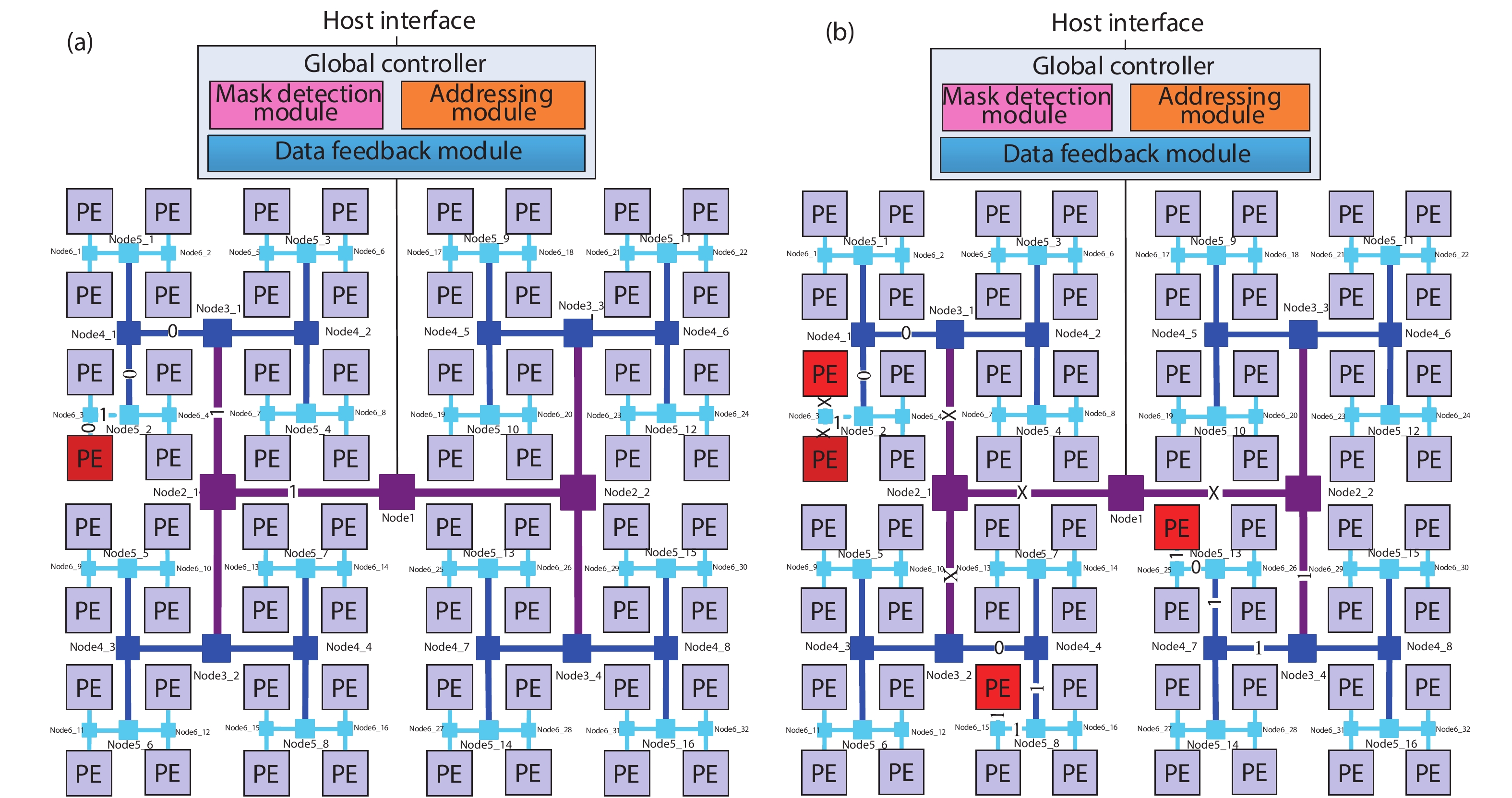
In order to improve the efficiency of reconfiguration (including the fast updating and invoking of reconfigurable context), minimize interconnection costs, and also control the power consumption, we propose HRM — a novel reconfiguration mechanism. The HRM leverages Huffman-coding-like addressing and mask addressing, which can be easily applied on a homogeneous thin-core PE array (for example, consisting with 1024 PEs). The HRM structure is shown in Fig. 1. In order to show it clearly, Fig. 1 only presents 8 × 8 PEs.
![]()
Figure 1.(Color online) The topology of HRM. (a) Unicast. (b) Multicast/broadcast.
HRM is designed from the idea of clock-tree with H-type, which can guarantee the minimal time skew so that the information can arrive at every destination at the same time. The video processing and graphics processing need some associated PEs to work together as a certain function unit. For example, the reconfigurable video processing system requires multiple PEs to execute the same task, such as intra-prediction (Intra), integer motion estimation (IME), fractional motion estimation (FME), motion compensation (MC), DeBlocking filter (DB), etc. And in graphics processing field, the vertex shading, the plane-clip, projection, 3D-Clip, pixel shading, primitive assemble unit, back-face culling, viewport transformation, fragment operating unit and so on are also need several PEs to work together[
The global controller determines the operating mode and selects the appropriate algorithm for PEs. HRM is used to transfer the instructions or configuration messages to a specific PE or associated PEs, and collect status information of each PE to the global controller. When the global controller transfers data to or from the PEs via HRM, it utilizes Huffman-coding-like code to address each PE. Using the 1024-PE array as an example, HRM addressing bus is of 10-bit width at the root (the bus end which connects to the controller). HRM will take 10-level turns to access the destination end (each PE). When the bit of the bus is logic ‘1’, HRM will take a right turn; If the bit[
With the Huffman-coding-like addressing and mask addressing method, HRM can transmit/receive four kinds of instruction/context information with 32-bit width:
(1) The operation instruction with issuing format of: 2-bit flag of ‘01’ + 30-bit RISC-like instruction.
(2) The ‘call’ instruction with issuing format of: 2-bit flag of ‘11’ + 16-bit invoking address + 14-bit extensible space.
(3) The broadcast SIMD/data-driven instruction with issuing format of: 2-bit flag of ‘10’ + 30-bit RISC-like instruction. In this format, the broadcast mask should be transmitted first with the 2-bit flag of ‘10’, and at each turn, the switch node will mark the transmitting direction according to the bit value. If that bit is logic ‘1’, the instruction sent next will be transmitted in both directions; as for logic ‘0’, the instruction sent next will be transmitted according to the address bit value.
(4) The status feedback with issuing format: 2-bit flag of ‘00’+30-bit extensible space. This is used for collecting the status of each computing resource for performance evaluation, and it is running parallel with the computing resource without disturbing the normal operation.
The global controller monitors the operating status of each functional unit, determines the operating mode, and selects a particular algorithm based on the performance evaluation model in real time for PEs. When the host interface accesses the array processor, the global controller receives the bus information from the host interface and judges whether the instruction is unicasted, multicasted, broadcasted, or fed back according to the flag.
4.2. PE array structure
The HRM is applied on the homogeneous thin-core PE array. In order to verify the availability of HRM, we also design a reconfigurable PE array. The proposed PE array is different from the CGRA-based multi-core architecture[
![]()
Figure 2.(Color online) Homogeneous thin-core PE array. (a) Inter –cluster communicate. (b) PE cluster. (c) Micro-architecture of PE.
The 1024 PE array consists of 64 clusters organized in 8 × 8 structure. In many applications, there exists remote data communication between different PEs. The adjacent interconnect and distributed memory cannot efficiently and flexibly handle such communications. We develop an inter-cluster communication structure which connects the PEC with a router (R) through network adapter (NA). The topology is shown in Fig. 2(a).
The PE communicates with the adjacent PE through four shared registers (RN, RE, RW,RS, which represents the four directions, north, east, west, and south respectively), which can be called the NEWS adjacent interconnect[
The PE can also be configured as data-driven mode for improving the performance and energy efficiency, which can be enabled or disabled by the control commands transmitted by HRM. As shown in Fig. 2(c), the bold lines indicate the control flow and data flow after the data-driven mode is enabled, and the control flow mainly includes the operation code and the data path reconstruction signal, where the dataflow comes from the last-level PE. When data-driven mode is enabled, the fetch stage, the decode stage, and the write back stage are stalled by the gated clock. The data from the last-level PE is directly transmitted to the execution unit, and the corresponding operation is performed according to the operation code received from the HRM, then the result is sent to the adjacent PE through four shared registers directly.
The instruction memory (IM) of each PE used to buffer the operating instructions/contexts. The operations of a particular application are stored in the IM as default configuration when power on the system. As the operating instruction is stored in the memory, the proposed reconfiguration mechanism may sound no different than fat binary. However, the IM also can receive run-time reconfiguration contexts from the global controller through the HRM based on the selected performance model. Under the help of HRM, the reorganized function running on one PE or several associated PEs can start simultaneously, which is very different from fat binary. With the instructions stored in default, or the real-time instructions passed from the global controller through HRM, the PEs can act as a specific function unit (FU) and operate at data-driven mode to improve performance while reducing power dissipation.
The data memory of the PE array is of distributed shared structure. Each PE has its own data memory with size of 512 B. In order to achieve the large memory size and low accessing latency, the RAMs in a PE cluster are shared logically through the column and row buses as shown in Fig. 3. In order to show it clearly, Fig. 3 only presents the memory shared structure of 4 PEs. As for the intra-cluster data access, a high-speed switching structure is realized, which can meet 16-channel data parallel read/write access.
![]()
Figure 3.(Color online) Distributed shared memory structure.
5. Prototype development and experimental setup
This section describes the architecture modeling software platform, RTL synthesis configuration, and FPGA prototype system.
5.1. Architecture modeling
In order to evaluate the feasibility of the proposed reconfigurable mechanism, we developed an architecture model using SystemC[
5.2. Design of HRM
According to the above analysis, the key to realize fast and dynamic reconstruction of reconfigurable array is HRM. Therefore, in this part, we further explain the hardware architecture of HRM in combination with Section 4 of HRM design ideas and methods. According to Fig. 1, the hardware architecture consists of two parts: a global controller and an H-type reconfiguration network.
Global controller: It is used to complete management of configuration information, monitoring of PE status, and data interaction with the host. The configuration information management module includes two parts: a configuration storage management module and a configuration network address generation module. The configuration storage manager generates a corresponding address according to the request sent by the host, accesses the corresponding configuration storage, and configures the network address generation module. The network address generator configures the addressing node according to the requirements. The data interaction on the host side mainly receives commands from the upper layer host and provides real-time feedback status information of the PE array.
H-type reconfiguration network: This network completes the delivery of configuration information and the collection of status information. In Fig. 1, each node in the H-type has two configurable registers, one for directional and one for mask. The directional controls the transmission in a single direction on the node, with left ‘0’ and right ‘1’. The mask controls the simultaneous transmission in both directions on the node. The mask control has a higher priority than the direction control. The entire data path is established by configuring these two registers on each node to achieve unicast, multicast and broadcast of the array. As shown in Fig. 1(a) (which consists of 8 × 8 PEs, inferring 6-bit addressing bus), after configuration the unicast mode is adopted, and the configuration information is sent to the destination PE through Node1_1, Node2_1, Node3_1, Node4_1, Node5_2, and Node6_3 in sequential order. Since the addressing of the PE (filled with red) takes six turns of right, right, left, left, right, and left, the address should be 110010. The multicast or broadcast mode is shown in Fig. 1(b). The configuration information arrives at Node2_1 and Node2_2 at the same time. The subsequent configuration process is similar to the unicast mode. When transfer a single configuration to a PE, the address and operation code are transferred in one pass[
5.3. Implementation of prototype system
We developed the hardware of proposed HRM and also the PE array using Verilog HDL. The circuit specification of the proposed architecture and the RSF architecture is shown in Table 1. The prototype system of the proposed approach is implemented in the BEE4 FPGA development board of BeeCube with the FPGA chip of XC6VLX550T, as shown in Fig. 4, which takes video processing as an example. The top left part shows the console on host machine, where the user can input the video sequence and reconfiguration contexts. The bottom left part shows the console of the BEE4, where user can configure the FPGA and enable it to execute. The bottom right part is BEE4 platform, where the proposed HRM and PE array are mapped into and running on. The top right part is the reconstruction image, where the user can observe the results intuitively. The prototype system can work at speed of up to 150 MHz, and the HRM can work at 440 MHz, which means that the proposed reconfigurable mechanism won’t be the bottleneck of the whole system. In Fig. 4, the program running on each PE is stored by default, so it is the power-on configuration of the PE array. In the next part, we will describe the reconfiguration process.
![]()
Figure 1.(Color online) The topology of HRM. (a) Unicast. (b) Multicast/broadcast.
6. Evaluation
In this section, we examine the reconfigurable process on the prototype platform. We check the whole system structure reorganization on video processing, graphics processing, the data-driven mode operation to achieve high performance and low power consumption, and then the comparison of reconfigurable process.
6.1. Application in video processing
Under the proposed HRM and associated PE array, we implemented one kind of video processing system, as shown in Fig. 5(a). While testing, we found that the FUs, such as Intra and MC, are the bottlenecks. Then we reorganized it to Fig. 5(b) in run-time. In Fig. 5, each module with different color presents different FU, and each FU occupies a PE cluster.
![]()
Figure 2.(Color online) Homogeneous thin-core PE array. (a) Inter –cluster communicate. (b) PE cluster. (c) Micro-architecture of PE.
In order to realize this reconfiguration, the contexts should be transferred are shown in Table 2. As shown in Fig. 5, when the array is initialized, PEC01 performs DCT algorithm and occupies 16 PEs. After reconfiguration, the cluster performs Intra prediction algorithm and occupies 2 PEs. We use 16→2 to indicate this change, so are the 15→8, 9→12, etc. The operation instructions can be transferred during the execution of last reconfiguration, so the reorganization of PE array only spend the time of call instructions’ transmission, which means the reconfiguration time is 55 clock cycles. In HReA, the contexts’ transmission is finished through router. And technically the PE’s reconfiguration will spend at least 2 cycles for each call-like context, i.e., it will spend 2× more time for reconfiguration. Fig. 6 shows the video processing results under two sequences.
![]()
Figure 5.(Color online) Organizations of video processing system. (a) Original organization of video processing system. (b) Video processing system with higher parallelism.
Meanwhile, we compared the power consumption of the new configuration of video processing with and without the power control. If left the unused PEs running in idle, the dynamic power dissipation is 286 mW; while in the HRM verison, we leverage the power control signal to disable the unnecessary PEs in this context, and the dynamic power dissipation is 139 mW. The power consumption reduced about 51%.
6.2. Application in graphics processing
We also apply the proposed HRM and associated PE array to graphics processing. Here we take a scene of viewport transform as an example. The scheme is mapped the graphics processing algorithm on 1 PE cluster. By reconfiguring the function of PE, the viewport transformation can be flexibly realized with lower computation cost[
![]()
Figure 7.Mapping of viewport transportation.
![]()
Figure 9.Data-driven mode mapping of six-tap filter. (a) Six-tap filter. (b) Data-driven mode mapping.
6.3. Realization of data-driven mode
Data-driven mode is used for the data intensive computation. We select the six-tap filter in fractional motion estimation (FME) algorithm of video encoding. FME performs motion search around the refinement center pointed to by integer motion estimation (IMV) and further refines the integer motion vectors (IMVs) into fractional MVs (FMVs) of quarter-pixel precision. FME interpolates half-pixels using a six-tap filter. The six-tap filter was expressed and realized in ASIC structure as shown in Fig. 9(a). In order to realize it in proposed structure, we map it on the PE array as shown in Fig. 9(b). All the configuration contexts are transferred from global controller through HRM, and each associated PE latch its own configuration information. Then the PE array works in this configuration. In such scenario, the working speed can reach 214 MHz in this FPGA. And if we utilize Verilog HDL to describe the six-tap filter directly and implemented it on the same FPGA, its operating frequency is 500 MHz. The results show that the performance of proposed reconfigurable structure is comparable to the ASIC circuit.
6.4. RTL-synthesis results
In order to evaluate the performance of the proposed architecture and the HRM, we synthesize the circuit using design compiler under the process of 90 nm CMOS technology. The results of area, critical delay, and power dissipation are shown in Table 3. The synthesis results show that the proposed approach has some advantages in speed, and area of 25.1%, 36.9%, respectively when compared with RSF, however, the power dissipation is higher, but still very low, about 1.96 mW. When compared with HReA, the speed advantage is about 21.6%, however, the HReA is implemented under the 65 nm CMOS technology. The HRM maximum operating frequency can reach 494.16 MHz. The instruction issuing operation is completed in one cycle, the instruction broadcasting operation is completed in 2 cycles, and the data feedback operation is completed in one cycle. Hence, we can predict that HRM will have a comparable speedup under the same technology. From Table 3, we can observe that the HRM only occupies 0.1% area of one PE cluster. The area cost can be negligible.
7. Conclusion
Prior reconfigurable architectures suffer from performance bottleneck due to the inadequate flexibility and low context switching speed. This paper proposes a fast reconfigurable mechanism —HRM and applies it in a massive homogeneous PE array to achieve the simultaneous movement of reconfiguration contexts among particular/related PEs in unicast, multicast, or broadcast modes and also control the power. We develop the HRM architecture model using SystemC, implement the HRM design in Verilog, simulate with Questasim, synthesize using Design Compiler, and implement on a FPGA board. Compared to the RSF and HReA, HRM can speedup critical delay by an average of 23.4%, and improve the context/algorithm switching performance by 2× while saving 36.9% area. In the context switching, HRM can shut down the unnecessary PEs which reduced 51% of dynamic power dissipation in one video processing configuration. Moreover, in the data-driven mode, the proposed PE array with HRM can achieve performance comparable to ASICs.
Acknowledgments
This work was supported by the National Natural Science Foundation of China (Nos. 61834005, 61602377, 61772417, 61802304, 61874087) and the Shaanxi International Science and Technology Cooperation Program No. 2018KW-006, Shaanxi Provincial Key R&D Plan under Grant No. 2017GY-060, and Shaanxi Province Co-ordination Innovation Project of Science and Technology under Grant No. 2016KTZDGY02-04-02.
References
[1] Z Yun, L Jiang, S Wang et al. Design of reconfigurable array processor for multimedia application. Multimed Tools Appl, 77, 3639(2018).
[2] X Shi, X Luo, J Liang et al. Frog: Asynchronous graph processing on GPU with hybrid coloring model. IEEE Trans Knowl Data Eng, 30, 29(2017).
[3] Y Wang, A Davidson, Y Pan et al. Gunrock: A high-performance graph processing library on the GPU. ACM SIGPLAN Notices, 51, 11(2016).
[4]
[5]
[6] R J Tian, L Jiang, J Y Deng et al. Design and implementation of reconfigurable viewport transformation unit in embedded GPU. Mini-Micro Syst, 39, 1074(2018).
[7]
[8]
[9] C Yang, Y Wang, X Wang et al. WRA: A 2.2-to-6.3 TOPS highly unified dynamically reconfigurable accelerator using a novel Winograd decomposition algorithm for convolutional neural networks. IEEE Trans Circuits Syst I, 66, 3480(2019).
[10] L Liu, Z Li, C Yang et al. Hrea: An energy-efficient embedded dynamically reconfigurable fabric for 13-dwarfs processing. IEEE Trans Circuits Syst II, 65, 381(2017).
[11] S M A H Jafri, M Daneshtalab, N Abbas et al. Transmap: Transformation based remapping and parallelism for high utilization and energy efficiency in CGRAs. IEEE Trans Comput, 65, 3456(2016).
[12]
[13] Y Kim, H Joo, S Yoon. Inter-coarse-grained reconfigurable architecture reconfiguration technique for efficient pipelining of kernel-stream on coarse-grained reconfigurable architecture-based multi-core architecture. IET Circuits, Devices Syst, 10, 251(2016).
[14]
[15]
[16]
[17]
[18]
[19]
[20] Y S Wang, L B Liu, S Y Yin et al. Hierarchical representation of on-chip context to reduce reconfiguration time and implementation area for coarse-grained reconfigurable architecture. Sci Chin Inform Sci, 56, 1(2013).
[21] Y Kim, R N Mahapatra. Dynamic context compression for low-power coarse-grained reconfigurable architecture. IEEE Trans Very Large Scale Integr Syst, 18, 15(2009).
[22] A Venkat, D M Tullsen. Harnessing ISA diversity: Design of a heterogeneous-ISA chip multiprocessor. ACM SIGARCH Comput Architect News, 42, 121(2014).
[23]
[24] J Y Deng, T Li, L Jiang et al. Design and optimization for multiprocessor interactive GPU. The Journal of China Universities of Posts and Telecommunications, 21, 85(2014).
[25] J Y Deng, T Li, L Jiang et al. Design and implementation of the graphics accelerator oriented to OpenGL. Journal of Xidian University, 42, 124(2015).
[26] J Y Deng, T Li, L Jiang et al. The design of multiprocessor interactive GPU MIGPU-9. J Comput Aid Des Comput Graph, 26, 1468(2014).
[27] X B Shen, Z X Liu, R Wang et al. The unified model of computer architectures. Chin J Computs, 30, 729(2007).
[28]
[29]
[30] X T Zhang, L Jiang, J Y Deng et al. Design and Implementation of global controller in reconfigurable video array processor. Microelectron Comput, 34, 75(2017).

Set citation alerts for the article
Please enter your email address
© Copyright 2018-2021 | Chinese Laser Press. All Rights Reserved 沪ICP备15018463号-20