• Photonics Research
  • Vol. 9, Issue 7, 1218 (2021)
Lei Tang1, Jiangshan Tang1, Haodong Wu1, Jing Zhang2、3, Min Xiao1、4, and Keyu Xia1、*
Author Affiliations
  • 1College of Engineering and Applied Sciences, National Laboratory of Solid State Microstructures, Collaborative Innovation Center of Advanced Microstructures, Nanjing University, Nanjing 210093, China
  • 2Department of Automation, Tsinghua University, Beijing 100084, China
  • 3Center for Quantum Information Science and Technology, Tsinghua National Laboratory for Information Science and Technology (TNList), Beijing 100084, China
  • 4Department of Physics, University of Arkansas, Fayetteville, Arkansas 72701, USA
  • show less
    DOI: 10.1364/PRJ.413286 Cite this Article Set citation alerts
    Lei Tang, Jiangshan Tang, Haodong Wu, Jing Zhang, Min Xiao, Keyu Xia. Broad-intensity-range optical nonreciprocity based on feedback-induced Kerr nonlinearity[J]. Photonics Research, 2021, 9(7): 1218 Copy Citation Text show less

    Abstract

    Nonreciprocal light propagation plays an important role in modern optical systems, from photonic networks to integrated photonics. We propose a nonreciprocal system based on a resonance-frequency-tunable cavity and intensity-adaptive feedback control. Because the feedback-induced Kerr nonlinearity in the cavity is dependent on the incident direction of light, the system exhibits nonreciprocal transmission with a transmission contrast of 0.99 and an insertion loss of 1.5 dB. By utilizing intensity-adaptive feedback control, the operating intensity range of the nonreciprocal system is broadened to 20 dB, which relaxes the limitation of the operating intensity range for nonlinear nonreciprocal systems. Our protocol paves the way to realize high-performance nonreciprocal propagation in optical systems and can also be extended to microwave systems.

    1. INTRODUCTION

    Nonreciprocal components are of significance for both classical and quantum photon-based information processing. Optical nonreciprocity can be achieved by using magneto-optical materials [14], spatiotemporal modulation [59], chiral light–matter interactions [1013], atomic microscopic Doppler effect [1416], macroscopic Doppler effect of moving atomic lattices [1719], optomechanical interactions [2022], and optical nonlinearities [2331]. Specifically, by using the nonlinearities of optical resonators, bias-free and integrated nonreciprocal devices can be realized [2628]. Despite constraints imposed by dynamic reciprocity [32] under simultaneous excitation from opposite ports, nonlinear nonreciprocal devices attract intense research for situations involving pulsed signals because they have advantages of being compatible with an on-chip platform. However, besides dynamic reciprocity, the nonreciprocity of nonlinear optical devices is crucially dependent on the intensity of incident light. Nonlinear nonreciprocal devices are constrained by a narrow operating intensity range [2326]. A number of nonlinear nonreciprocal devices are affected by a trade-off between the maximum forward transmission and the nonreciprocal intensity range (NRIR) [2528]. Cascaded Fano–Lorentzian nonlinear resonators have been demonstrated to relax the limitation to some degree [27,28]. However, it remains a big challenge to realize nonlinear nonreciprocal devices with a high transmission contrast, broad bandwidth, wide NRIR, and low insertion loss simultaneously.

    Feedback control is an important method to manipulate the dynamic evolution of the system [33,34], and it can generate and amplify nonlinearity in a resonator [35,36]. Here we demonstrate a novel and simple nonreciprocal optical system based on a cavity with resonance frequency tuned by a feedback control system via the electro-optic (EO) effect. A part of the information of the cavity can be detected by a detector. The output current of the detector is fed back to an electric circuit to generate effective Kerr nonlinearity in the cavity. In our designed system, the feedback current intensities are dependent on the incident directions of light, leading to directional, in other words direction-dependent, Kerr nonlinearities and subsequently nonreciprocal light transmissions. To obtain a broad NRIR, we explore intensity-adaptive feedback control to dynamically amplify and tune the induced Kerr nonlinearity. As a result, our designed nonreciprocal optical system exhibits a transmission contrast of 0.99 and a broad NRIR at the same time.

    2. SYSTEM AND MODEL

    The basic system depicted in Fig. 1(a) consists of a Fabry–Perot (FP) cavity containing an EO nonlinear crystal, e.g., LiNbO3, and an intensity-adaptive feedback circuit. The feedback circuit includes mainly an electric filter, an electric amplifier, and two photodetectors (PDs). For a forward input a^in, a portion of the transmitted light through the beam splitter (BS) is reflected by the cavity and monitored by PD1. Its output is filtered and amplified to drive the EO nonlinear crystal in the cavity. Because of the Pockels effect, the modulated EO nonlinear crystal can induce a resonance frequency shift to the cavity. However, for a backward input b^in, a fraction of the transmitted light through the cavity is partly reflected by BS and monitored by PD1. Through the feedback circuit, the output current of PD1 drives the EO nonlinear crystal and induces a resonance frequency shift different from the forward case. Thus, the opposite-direction inputs can induce different feedback current intensities, yielding different resonance frequency shifts. As a result, the direction-dependent feedback current leads to directional Kerr nonlinearity in the cavity and the nonreciprocal transmission of the system. Note that a certain feedback current from PD1 produces the same resonance frequency shift of the cavity in opposite input directions. The intensity of the feedback current caused by feedback light incident on PD1 is dependent on the direction of the input light. This dependence causes the directional resonance frequency shift of the cavity, as depicted in Fig. 1(b). The basic idea is the following: at the beginning of the input light entering the cavity, the input is off resonance with the cavity, and the detuning Δin is large. For the forward input, the feedback-induced resonance frequency shift of the cavity is close to the detuning but with opposite signs. Thus, the shift “pulls” the cavity to be near resonance with the input. As a result, the forward transmission is high. In contrast, the feedback-induced resonance frequency shift in the backward-input case is small and cannot compensate for the initial detuning. The off-resonance backward transmission is weak. In this arrangement, we obtain a transmission contrast of 0.99. It is worth noting that our system is still under the constraint imposed by dynamic reciprocity. Therefore, to break the time-reversal symmetry, the forward and backward inputs are applied to the system separately in time.

    Schematic diagram of the nonreciprocal propagation system. (a) Schematic of the system consisting of a feedback circuit and an FP cavity containing an EO nonlinear crystal. The feedback circuit includes a low-pass filter (LPF), an electric amplifier (Amp), and two photodetectors (PD1 and PD2). Left-handed incident light propagates in the forward direction and transmits through the beam splitter (BS) to excite the cavity. The reflected light of the cavity is reflected by the BS and a mirror successively, and then it is detected by PD1. The output current of PD1 is filtered by the LPF and amplified by the amplifier. Then the current modulates the EO nonlinear crystal and changes the transmission of the cavity. PD2 is used to monitor a fraction of the left-handed incident light and control the gain of the amplifier. Right-handed incident light moves in the backward direction, transmits through the cavity, and is reflected by the BS and the mirror and then captured by PD1. In the same way, the output current drives the EO nonlinear crystal and modulates the transmission of the cavity. (b) Transmission spectrum of the system. Black curves are for transmissions of the FP cavity without feedback. Blue (red) curves are for transmissions of the feedback-modulated cavity in the forward (backward) case. Green vertical bar is for the frequency of incident light (ωin). Black vertical bar is for one of the eigenfrequencies of the cavity (ω0).

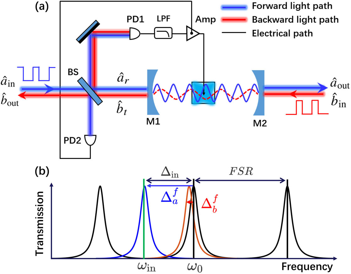
    Figure 1.Schematic diagram of the nonreciprocal propagation system. (a) Schematic of the system consisting of a feedback circuit and an FP cavity containing an EO nonlinear crystal. The feedback circuit includes a low-pass filter (LPF), an electric amplifier (Amp), and two photodetectors (PD1 and PD2). Left-handed incident light propagates in the forward direction and transmits through the beam splitter (BS) to excite the cavity. The reflected light of the cavity is reflected by the BS and a mirror successively, and then it is detected by PD1. The output current of PD1 is filtered by the LPF and amplified by the amplifier. Then the current modulates the EO nonlinear crystal and changes the transmission of the cavity. PD2 is used to monitor a fraction of the left-handed incident light and control the gain of the amplifier. Right-handed incident light moves in the backward direction, transmits through the cavity, and is reflected by the BS and the mirror and then captured by PD1. In the same way, the output current drives the EO nonlinear crystal and modulates the transmission of the cavity. (b) Transmission spectrum of the system. Black curves are for transmissions of the FP cavity without feedback. Blue (red) curves are for transmissions of the feedback-modulated cavity in the forward (backward) case. Green vertical bar is for the frequency of incident light (ωin). Black vertical bar is for one of the eigenfrequencies of the cavity (ω0).

    PD2 is used to monitor the intensity of the forward incident light. A fraction of forward incident light is reflected by BS and detected by PD2, whose output modulates the gain of the electric amplifier. In this way, the gain of the electric amplifier is adjusted according to the input intensity, which is proportional to |a^in|2. Utilizing this intensity-adaptive feedback control, the NRIR can be greatly broadened without reducing transmission contrast or insertion loss.

    A. Forward Propagation

    For the forward case, the feedback current produced by PD1 is iaf(t)=ξγa^r(t)a^r(t),where ξ is the photoelectric conversion efficiency of PD1, and γ is the reflection coefficient of BS. According to the input–output relation of an optical cavity [37,38], the reflected field operator for the cavity is given in terms of the input and intracavity field operators as a^r(t)=1γa^in+κex1a^,where a^ is the annihilation operator for the cavity mode excited by forward incident light, a^in is the annihilation operator for the forward incident field, and κex1 is the decay rate caused by the cavity mirror (M1). According to Eqs. (1) and (2), the feedback current is iaf(t)=ξγ[(1γ)|αin|2+κex1|α|22κex1(1γ)Re(αin*α)],where the coherent amplitudes of the input field and the intracavity field are given by αin=a^in and α=a^, respectively. An input power Pin corresponds to an input photon flux |αin|2=Pin/ωin.

    Now we derive the feedback current acting on the optical cavity after a low-pass electrical filter. The feedback current is filtered by a low-pass filter with an impulse response function h(t)=(2ωc/3)exp(ωct/2)sin(3ωct/2), where ωc is the cutoff frequency. When the incident light enters the cavity at the beginning time period, the detuning with the cavity is large and causes oscillation in the feedback. We use this low-pass filter to block the rapidly oscillating component in the feedback-induced frequency shift. The high-frequency components of the feedback current caused by a high-power input can be filtered. The filtered feedback current is then amplified and modulates the EO nonlinear crystal inside the cavity, yielding a resonance frequency shift: Δaf(t)=χG0tiaf(τ)h(tτ)dτ,where χ is the coefficient of the EO nonlinear process, and G is the gain of the electric amplifier. We define conversion-amplification coefficient AχGξ for later convenience. Combining Eqs. (3) and (4), the cavity-excitation-dependent (i.e., |α|2-dependent) resonance frequency shift can be written as Δaf(t)=Aγ0t{(1γ)|αin(τ)|2+κex1|α(τ)|22κex1(1γ)Re[αin*(τ)α(τ)]}h(tτ)dτ.

    Working in a frame rotating at the incident field frequency ωin, the system can be modeled as an effective Kerr nonlinear cavity driven by the forward input αin described by the Hamiltonian Hfw=(Δin+Δaf)a^a^+iκex1(1γ)(αina^αin*a^),where Δin=ω0ωin, ω0 is resonance frequency of the cavity in the absence of feedback, and κ is the total cavity decay rate, including the decay rates (κex1/κex2) caused by cavity mirrors (M1/M2) and the intrinsic decay rate κi caused by the absorption and scattering of the EO nonlinear crystal, i.e., κ=κex1+κex2+κi.

    For a classical field input, we can apply the mean-field approximation to the cavity mode α=a^. In this case, the feedback produces an effective Kerr nonlinearity to the cavity. The cavity mode amplitude a^ in the mean-field approximation evolves with time according to α˙=i(Δin+Δaf)α+κex1(1γ)αinκ2α.

    According to the input–output relation a^out=κex2a^, the forward transmission amplitude is defined as tfw=a^out/αin. Thus, the corresponding forward transmission coefficient is Tfw=|tfw|2.

    We can numerically solve Eqs. (5) and (7) by using the four-order Runge–Kutta method to find the time evolution of the resonance frequency shift and the forward transmission. Additionally, it is possible to obtain an analytical expression for the steady-state transmission. For the forward case, we assume the feedback-induced resonance frequency shift stably remains at a certain value Δa,ssf when the system reaches the steady state. We define the residual detuning as δaΔin+Δa,ssf. In this case, the steady-state solution of Eq. (7) is αss=κex1(1γ)αiniδa+κ/2.

    According to the input–output relation and tfw=a^out/αin, the steady-state forward transmission is Tfw=4κex1κex2(1γ)4δa2+κ2.

    B. Backward Propagation

    For the backward case, the intensity of feedback current produced by PD1 is ibf(t)=ξγb^t(t)b^t(t).

    According to the input–output relation, the transmitted field operator for the cavity is given by b^t(t)=κex1b^,where b^ is the annihilation operator for the cavity mode excited by backward incident light. Note that a^ and b^ express the same cavity mode with different denotations to distinguish the opposite incident directions. Combining Eqs. (10) and (11), the feedback current can be expressed as ibf(t)=ξγ·κex1|β|2, with the coherent amplitude of the intracavity field β=b^.

    The same with the forward case, the filtered feedback current is amplified and modulates the crystal with the same conversion-amplification coefficient A. So the resonance frequency shift is Δbf(t)=Aγκex10t|β(τ)|2h(tτ)dτ.

    The Hamiltonian for the backward case is given by Hbw=(Δin+Δbf)b^b^+iκex2(βinb^βin*b^),where βin is the backward incident amplitude. The input power Pin yields the input photon flux |βin|2=Pin/ωin. In the mean-field approximation β=b^, the cavity also includes Kerr nonlinearity due to the feedback control. This effective Kerr nonlinearity coefficient is different from the forward case. The evolution of the cavity mode b^(t) in the mean-field approximation is given by β˙=i(Δin+Δbf)β+κex2βinκ2β.

    Because of the input–output relations b^out=1γb^t and b^t=κex1b^, the backward transmission amplitude is given by tbw=b^out/βin, and the corresponding backward transmission coefficient is Tbw=|tbw|2. The time evolution of the frequency shift and the transmission in the backward case can be found by numerically solving Eqs. (12) and (14).

    We assume the resonance frequency shift remains at Δb,ssf, and define the residual detuning as δbΔin+Δb,ssf. Thus, we obtain the steady-state solution to Eq. (14) as βss=κex2βiniδb+κ/2.

    Using the input–output relations and tbw=b^out/βin, we obtain the steady-state backward transmission Tbw=4κex1κex2(1γ)4δb2+κ2.

    For simplicity, we assume κex1=κex2=κex, such that κ=2κex+κi throughout the investigation below.

    3. RESULTS

    A. Nonreciprocal Steady-State Transmission

    We numerically solve Eqs. (7) and (14) with the four-order Runge–Kutta method to find the time evolution of the state of the cavity and its transmission. As shown in Fig. 2, the system reaches the steady state (α˙0 and β˙0) after evolving a time period such that κext1. Excited from opposite sides with the input fields with equal power (Pin=830ωinκex) and the same detuning (Δin=15κex), the system reaches a steady state after a hysteresis (τh138κex1). The steady-state forward and backward transmissions shown in Fig. 2(a) are Tfw0.70 and Tbw0.005, respectively. The system exhibits a transmission contrast of η=(TfwTbw)/(Tfw+Tbw)0.99 [10,17] and an insertion loss of =10log10(Tfw)1.5dB.

    Nonreciprocal transmission properties. (a) Nonreciprocal transmission. Blue (red) curve is for the forward (backward) transmission Tfw (Tbw). (b) Average photon number inside the cavity. Blue (red) curve is for the forward (backward) case. (c) Feedback-induced resonance frequency shifts. Blue (red) curve is for the frequency shift in forward (backward) case. In the inset, the black dashed curve indicates the input detuning of −Δin=15κex. For the steady state, the feedback-induced frequency shift for the forward (backward) case is Δa,ssf≈14.6κex (Δb,ssf≈0.5κex). All calculations are obtained by solving Eqs. (7) and (14) numerically with parameters: γ=0.01, κi=0.2κex, ωc=190κex, A=12, Δin=−15κex, and Pin/ℏωin=830κex.

    Figure 2.Nonreciprocal transmission properties. (a) Nonreciprocal transmission. Blue (red) curve is for the forward (backward) transmission Tfw (Tbw). (b) Average photon number inside the cavity. Blue (red) curve is for the forward (backward) case. (c) Feedback-induced resonance frequency shifts. Blue (red) curve is for the frequency shift in forward (backward) case. In the inset, the black dashed curve indicates the input detuning of Δin=15κex. For the steady state, the feedback-induced frequency shift for the forward (backward) case is Δa,ssf14.6κex (Δb,ssf0.5κex). All calculations are obtained by solving Eqs. (7) and (14) numerically with parameters: γ=0.01, κi=0.2κex, ωc=190κex, A=12, Δin=15κex, and Pin/ωin=830κex.

    According to Eqs. (5) and (12), we obtain the feedback-induced resonance frequency shifts [Fig. 2(c)]. For the forward case, the feedback-induced resonance frequency shift begins oscillating from an initial frequency shift determined by the input, and locks to a certain value close to the input detuning, i.e., Δa,ssfΔin, and δa/κex0, at the end of hysteresis. Once the feedback-induced shift is locked, the cavity mode is highly excited [Fig. 2(b)]. As a result, the feedback control “pulls” the detuned resonator to near resonance, yielding a high forward transmission. However, for the backward case, the feedback-induced frequency shift is negligible, compared with the incident detuning, i.e., Δb,ssfΔin, and δbΔin. Thus, the cavity is weakly excited, as shown in Fig. 2(b). It means that the feedback control hardly changes the initial detuned state of the system. As a result, the backward transmission is low.

    According to the steady-state analytical solutions, we below investigate how the nonreciprocal transmissions of the system are affected by the reflection coefficient of the BS and the intrinsic loss of the cavity. From the numerical results shown in Fig. 2(c), we can find the steady-state feedback-induced resonance frequency shifts Δa,ssf14.6κex and Δb,ssf0.5κex for the forward and backward cases, respectively. We can set the optimized residual detunings δa=0.4κex and δb=Δin to calculate the analytical steady-state transmissions with Eqs. (9) and (16). We also compare our analytic formula with numerical solutions to Eqs. (7) and (14). It can be seen in Fig. 3 that the numerical results of steady-state transmissions are in excellent agreement with the analytical solutions.

    Analytical and numerical steady-state results. Solid curves are for analytical results, and dots are for numerical results. (a) Blue (red) curve represents forward (backward) transmission versus log10(γ). (b) Blue (red) curve is for transmission contrast η (insertion loss ℒ) versus log10(γ) for κi=0.2κex. (c) Blue (red) curve represents forward (backward) transmission versus κi. (d) Blue (red) curve is for transmission contrast (insertion loss) versus κi for γ=0.01. Other parameters are ωc=190κex, A=12, and Δin=−15κex. For numerical calculations, the incident intensities are optimized values for the maximal forward transmissions.

    Figure 3.Analytical and numerical steady-state results. Solid curves are for analytical results, and dots are for numerical results. (a) Blue (red) curve represents forward (backward) transmission versus log10(γ). (b) Blue (red) curve is for transmission contrast η (insertion loss ) versus log10(γ) for κi=0.2κex. (c) Blue (red) curve represents forward (backward) transmission versus κi. (d) Blue (red) curve is for transmission contrast (insertion loss) versus κi for γ=0.01. Other parameters are ωc=190κex, A=12, and Δin=15κex. For numerical calculations, the incident intensities are optimized values for the maximal forward transmissions.

    It can be seen in Figs. 3(a) and 3(b) that the system exhibits the high insertion loss for γ>0.1, but the transmission contrast is independent of γ, satisfying the steady-state analytical solutions of η=2(δb2δa2)/[2(δb2+δa2)+κ2]. As shown in Figs. 3(c) and 3(d), a stronger intrinsic loss causes a higher insertion loss but the transmission contrast remains nearly constant in spite of small changes in the intrinsic loss, owing to 2(δb2+δa2)κ2.

    The forward and backward transmissions are dependent on the input light power (Pin) and the detuning between the input and the cavity (Δin). We show the numerically calculated steady-state forward and backward transmissions as a function of the input power and detuning in Figs. 4(a) and 4(b). For the input detuning with a positive value, the feedback will “push” the cavity resonance farther away from the input, suppressing transmission in both directions. For a negative detuning Δin and a moderate input power, e.g., Pin=500ωinκex, if |Δin| is large, the feedback-induced frequency shift cannot be large enough to compensate for this negative detuning. In this case, the cavity will still be off resonance with the input, preventing the transmission in both directions. If the detuning is too small, the feedback in the forward case will pull the cavity frequency to go beyond the resonance, also blocking the transmission. But for the backward case, the feedback is always too small to compensate for the initial detuning Δin, resulting in a low backward transmission.

    Steady-state transmissions of the non-adaptive feedback control system. (a), (b) Forward and backward transmissions versus input intensities and the detunings. (c) Forward (blue curve) and backward (red curve) transmissions versus input intensities for Δin=−15κex [white dotted transverse lines in (a) and (b)]. (d) Forward (blue curve) and backward (red curve) transmissions versus detunings for Pin/ℏωin=830κex [white dotted vertical lines in (a) and (b)]. All calculations are obtained by solving Eqs. (7) and (14) numerically with parameters: γ=0.01, κi=0.2κex, ωc=190κex, and A=12.

    Figure 4.Steady-state transmissions of the non-adaptive feedback control system. (a), (b) Forward and backward transmissions versus input intensities and the detunings. (c) Forward (blue curve) and backward (red curve) transmissions versus input intensities for Δin=15κex [white dotted transverse lines in (a) and (b)]. (d) Forward (blue curve) and backward (red curve) transmissions versus detunings for Pin/ωin=830κex [white dotted vertical lines in (a) and (b)]. All calculations are obtained by solving Eqs. (7) and (14) numerically with parameters: γ=0.01, κi=0.2κex, ωc=190κex, and A=12.

    For a specific value of the detuning Δin=15κex, the system exhibits nonreciprocal transmission versus incident power [Fig. 4(c)]. The maximal transmission contrast can be η=0.99, and the maximal forward transmission reaches Tfw=0.70. Referring to Refs. [25,28], we define the NRIR as the ratio of input power from opposite propagation directions that meet a special transmission contrast. For instance, to meet η=0.99, NRIR(0.99)=10log10(Pin2/Pin1)1.4dB, where Pin,1=634ωinκex and Pin,2=876ωinκex are the lower and upper power boundaries of the NRIR, respectively, as shown by the green area in Fig. 4(c).

    The nonreciprocal transmission as a function of the detuning is shown in Fig. 4(d) for a fixed incident power of Pin=830ωinκex as an example. As shown by the green area in Fig. 4(d), the nonreciprocal bandwidth meeting η=0.99 and 3dB is about 24.2κex. Within this nonreciprocal bandwidth, the backward transmission and transmission contrast almost remain unchanged, but the forward transmission linearly decreases with the detuning |Δin|.

    B. Intensity-Adaptive Feedback

    When the conversion-amplification coefficient (A) is fixed, the system holds nonreciprocal transmissions only over a small range of the incident intensity, as shown in Fig. 4(c). To broaden the NRIR, we apply intensity-adaptive feedback control to the system. PD2 is used to monitor the power of incident light (Pin) and control the gain of the electric amplifier (G), which are proportional to |αin|2 and A, respectively. As a result, the conversion-amplification coefficient adjusts with the incident intensity.

    At the beginning of the light incident into the system, the cavity mode is not excited, i.e., α=0, as shown in Fig. 2(b). According to Eq. (5), we define the input-induced resonance frequency shift Δa,infAγ(1γ)Pin/ωin,where the input power Pin is determined by |αin|2 in the forward case and |βin|2 in the backward case. We assume that the optimal forward transmission is Tfw, corresponding to an optimal input power Pinopt. The adaptive feedback circuit generates an optimized input-induced frequency shift Δa,inf,opt=Aγ(1γ)Pinopt/ωin. To maintain the optimal forward transmission, we need to use the adaptive circuit to fix this input-induced resonance frequency shift to Δa,inf,opt. To do so, we can set the intensity-adaptive amplification coefficient to A˜=ωinΔa,inf,optγ(1γ)Pin,for different input powers Pin. In this way, for various input light intensities, the system beginning with the same input-induced frequency shift Δa,inf,opt will evolve to the same steady state, yielding the same forward transmission Tfw. In the backward case, the feedback circuit shares the same amplification coefficient A˜ with the forward case. In intensity-adaptive feedback control, the coefficient A in Eqs. (5) and (12) is replaced with A˜.

    From numerical results shown as an example in Fig. 4(c), for a specific incident power range, the maximal forward transmission of Tfw0.70 is obtained for optimal parameters A=12 and γ=0.01. We take the upper boundary Pinopt=876ωinκex for optimal input power. To improve the NRIR, the system needs to adjust the coefficient A˜ according to Eq. (18) via the intensity-adaptive feedback circuit. In consideration of experimental feasibility, 1000-fold current gain of an electric amplifier has been achieved [39]. Here we set 1A˜100, varying over 20 dB.

    The steady-state forward and backward transmissions of the intensity-adaptive feedback control system are shown in Figs. 5(a) and 5(b). Compared with the non-adaptive feedback system shown in Figs. 4(a) and 4(b), the intensity-adaptive feedback system exhibits a broader NRIR for incident light with some certain frequencies. For instance, for a specific value of the detuning Δin=15κex, the NRIR(0.99) is greatly improved to 20 dB. Within the NRIR, the forward transmission Tfw and the transmission contrast η maintain 0.70 and 0.99, respectively. At the same time, the backward transmission Tbw is also extremely low, as is shown in Fig. 5(c).

    Steady-state transmissions of intensity-adaptive feedback control system. (a), (b) Forward and backward transmissions versus input intensities and detunings. (c) Blue (red) line is for forward (backward) transmission versus input intensities for Δin=−15κex [white dotted line in (a) and (b)]. (d) Conversion-amplification coefficients versus input intensities. All calculations are obtained with parameters: γ=0.01, κi=0.2κex, ωc=190κex, and Δa,inf,opt=104κex.

    Figure 5.Steady-state transmissions of intensity-adaptive feedback control system. (a), (b) Forward and backward transmissions versus input intensities and detunings. (c) Blue (red) line is for forward (backward) transmission versus input intensities for Δin=15κex [white dotted line in (a) and (b)]. (d) Conversion-amplification coefficients versus input intensities. All calculations are obtained with parameters: γ=0.01, κi=0.2κex, ωc=190κex, and Δa,inf,opt=104κex.

    To improve the NRIR, the coefficient A˜, limited by the performance of the electric amplifier of the feedback circuit, adaptively adjusts to different incident intensities [Fig. 5(d)]. According to Eq. (18), A˜ is inversely proportional to the input power (Pin). Therefore, the NRIR is determined by the lower boundary A˜L and the upper boundary A˜U of A˜, so NRIR=10log10(A˜U/A˜L). For instance, if 1A˜1000, varying over 30 dB, NRIR(0.99) is broadened to 30 dB.

    C. Nonreciprocal Pulse Transmission

    To avoid the dynamic reciprocal problem by temporal multiplex, we input pulsed signals into the system from two opposite directions. Rectangularly pulsed signals are incident in both forward and backward directions with a long enough delay τd, so that the temporal overlap in the system between the forward and backward propagating pulses can be avoided. We assume the time delay of feedback circuit τf is short enough, and the pulse duration τp is longer than the feedback delay and hysteresis duration τh but shorter than the pulse delay, i.e., τf,τhτp<τd. We take the pulse repetition interval 400πκex1, and τp=400π/3κex1, τd=200πκex1. The transmissions of pulsed signals in two opposite directions are shown in Fig. 6. The upper panel shows high transmissions of the pulse trains in the forward direction, while the lower panel indicates very low backward transmissions of the pulse streams.

    Propagation of rectangle pulses in forward and backward directions. Solid curves are the input rectangle pulse trains, and dashed curves are the transmitted pulses. Blue (red) curve shows the forward (backward) propagation of the pulses. τp is the pulse duration, and τd is the pulse delay between forward-input and backward-input pulses. All calculations are obtained by solving Eqs. (7) and (14) numerically with parameters: γ=0.01, κi=0.2κex, ωc=190κex, A=12, Δin=−15κex, and Pin/ℏω=830κex. The hysteresis duration τh is about 138κex−1.

    Figure 6.Propagation of rectangle pulses in forward and backward directions. Solid curves are the input rectangle pulse trains, and dashed curves are the transmitted pulses. Blue (red) curve shows the forward (backward) propagation of the pulses. τp is the pulse duration, and τd is the pulse delay between forward-input and backward-input pulses. All calculations are obtained by solving Eqs. (7) and (14) numerically with parameters: γ=0.01, κi=0.2κex, ωc=190κex, A=12, Δin=15κex, and Pin/ω=830κex. The hysteresis duration τh is about 138κex1.

    4. DISCUSSION AND CONCLUSION

    We proposed a feedback-induced nonreciprocal optical system using the experimentally existing technique. The frequency-tunable cavity can be made by using a 2 cm long FP cavity consisting of two mirrors with reflectivity of R=98% and a 0.15 cm long LiNbO3 nonlinear crystal. The external loss of the cavity caused by the two mirrors is calculated to be about κex2π×22.1MHz. The LiNbO3 crystal typically has an absorption loss of 0.3 m−1. We assume that two ends of the crystal are coated with 99.9% anti-reflection coating, leading to a total internal cavity loss of κi2π×5.4MHz0.2κex. In such design, the free spectral range (FSR) of the cavity is calculated to be FSR311κex, which ensures that the input detunings Δin and the resonance frequency shifts Δa(b)f cannot exceed the FSR and retains the system in a single cavity mode. Note that all our calculation results meet the conditions of FSR>{Δin,Δa(b)f}. The higher the input power Pin, the larger the feedback-induced shift Δa(b)f and the required cut-off frequency ωc. In some sense, the aforementioned conditions related to FSR also limit the applicable highest Pin and thus the available NRIR.

    Alternatively, the tunable cavity can also be realized by utilizing an FP cavity attached to a piezoelectric element [40]. The feedback signals drive the piezo to produce the resonance frequency shifts. This setup with much smaller intrinsic cavity loss can achieve a lower insertion loss, as shown in Fig. 3(d).

    Our proposed method can also be applied to a microwave system. In the microwave system, the frequency-tunable FP cavity can be replaced with a microwave resonator (transmission-line resonator) made from a superconducting electronic circuit [41,42]. The feedback signals can change the frequency of the electric field in transmission line resonators through the tunable inductance of a superconducting quantum interference device (SQUID) [35,43,44], leading to resonance frequency shifts. Thus, in the same way, nonreciprocal microwave transmission can be realized by utilizing direction-dependent feedback signals. Moreover, a microwave-frequency photon source, BS, filter, amplifier, and detectors can be integrated on a chip [45]. Thus, nonreciprocal transmission of pulsed microwave signals can also be realized on-chip with our protocol.

    In principle, fast switching can also isolate the reflected pulses from the pulsed input if the arriving time is precisely known. However, conventional switching is reciprocal because it does not break the time-reversal symmetry in any sense. On the other hand, the realization of a high-speed photonic switch is changing [28,46].

    In our design, the feedback current is generated by the optical signal itself and creates an effective Kerr nonlinearity to the optical subsystem. Our nonlinear nonreciprocal device breaks the time-reversal symmetry, and the scattering matrix is asymmetric when the input and reflected pulses do not arrive at the same time [47]. Our feedback approach takes a step towards isolation of pulsed signals and has the potential to bypass the constraint due to dynamic reciprocity, if the reflected pulses are delayed by a long enough time from the arrival of the input pulsed signal.

    In conclusion, we have explored feedback control to induce a directional Kerr nonlinearity in the cavity to achieve nonreciprocal transmission. By using intensity-adaptive feedback, we have realized a broad NRIR maintaining the transmission contrast of 0.99. Our protocol can also be implemented in a superconducting electronic circuit for nonreciprocal microwave transmission. Despite our system being subject to dynamic reciprocity, we have presented a general method to solve the outstanding challenge of integrated nonreciprocal devices. The proposed scheme promises useful applications in situations involving pulsed signals.

    References

    [1] H. Iwamura, S. Hayashi, H. Iwasaki. A compact optical isolator using a Y3Fe5O12 crystal for near infra-red radiation. Opt. Quantum Electron., 10, 393-398(1978).

    [2] D. J. Gauthier, P. Narum, R. W. Boyd. Simple, compact, high-performance permanent-magnet Faraday isolator. Opt. Lett., 11, 623-625(1986).

    [3] H. Dötsch, N. Bahlmann, O. Zhuromskyy, M. Hammer, L. Wilkens, R. Gerhardt, P. Hertel, A. F. Popkov. Applications of magneto-optical waveguides in integrated optics: review. J. Opt. Soc. Am. B, 22, 240-253(2005).

    [4] L. Bi, J. Hu, P. Jiang, D. H. Kim, G. F. Dionne, L. C. Kimerling, C. A. Ross. On-chip optical isolation in monolithically integrated non-reciprocal optical resonators. Nat. Photonics, 5, 758-762(2011).

    [5] H. Lira, Z. Yu, S. Fan, M. Lipson. Electrically driven nonreciprocity induced by interband photonic transition on a silicon chip. Phys. Rev. Lett., 109, 033901(2012).

    [6] Z. Yu, S. Fan. Complete optical isolation created by indirect interband photonic transitions. Nat. Photonics, 3, 91-94(2009).

    [7] N. A. Estep, D. L. Sounas, J. Soric, A. Alù. Magnetic-free non-reciprocity and isolation based on parametrically modulated coupled-resonator loops. Nat. Phys., 10, 923-927(2014).

    [8] D. L. Sounas, A. Alù. Non-reciprocal photonics based on time modulation. Nat. Photonics, 11, 774-783(2017).

    [9] C. W. Peterson, W. A. Benalcazar, M. Lin, T. L. Hughes, G. Bahl. Strong nonreciprocity in modulated resonator chains through synthetic electric and magnetic fields. Phys. Rev. Lett., 123, 063901(2019).

    [10] K. Xia, G. Lu, G. Lin, Y. Cheng, Y. Niu, S. Gong, J. Twamley. Reversible nonmagnetic single-photon isolation using unbalanced quantum coupling. Phys. Rev. A, 90, 043802(2014).

    [11] L. Tang, J. Tang, W. Zhang, G. Lu, H. Zhang, Y. Zhang, K. Xia, M. Xiao. On-chip chiral single-photon interface: isolation and unidirectional emission. Phys. Rev. A, 99, 043833(2019).

    [12] C. Sayrin, C. Junge, R. Mitsch, B. Albrecht, D. O’Shea, P. Schneeweiss, J. Volz, A. Rauschenbeutel. Nanophotonic optical isolator controlled by the internal state of cold atoms. Phys. Rev. X, 5, 041036(2015).

    [13] M. Scheucher, A. Hilico, E. Will, J. Volz, A. Rauschenbeutel. Quantum optical circulator controlled by a single chirally coupled atom. Science, 354, 1577-1580(2016).

    [14] K. Xia, F. Nori, M. Xiao. Cavity-free optical isolators and circulators using a chiral cross-Kerr nonlinearity. Phys. Rev. Lett., 121, 203602(2018).

    [15] S. Zhang, Y. Hu, G. Lin, Y. Niu, K. Xia, J. Gong, S. Gong. Thermal-motion-induced non-reciprocal quantum optical system. Nat. Photonics, 12, 744-748(2018).

    [16] C. Liang, B. Liu, A.-N. Xu, X. Wen, C. Lu, K. Xia, M. K. Tey, Y.-C. Liu, L. You. Collision-induced broadband optical nonreciprocity. Phys. Rev. Lett., 125, 123901(2020).

    [17] D.-W. Wang, H.-T. Zhou, M.-J. Guo, J.-X. Zhang, J. Evers, S.-Y. Zhu. Optical diode made from a moving photonic crystal. Phys. Rev. Lett., 110, 093901(2013).

    [18] S. A. R. Horsley, J.-H. Wu, M. Artoni, G. C. La Rocca. Optical nonreciprocity of cold atom Bragg mirrors in motion. Phys. Rev. Lett., 110, 223602(2013).

    [19] H. Ramezani, P. K. Jha, Y. Wang, X. Zhang. Nonreciprocal localization of photons. Phys. Rev. Lett., 120, 043901(2018).

    [20] S. Manipatruni, J. T. Robinson, M. Lipson. Optical nonreciprocity in optomechanical structures. Phys. Rev. Lett., 102, 213903(2009).

    [21] Z. Shen, Y.-L. Zhang, Y. Chen, C.-L. Zou, Y.-F. Xiao, X.-B. Zou, F.-W. Sun, G.-C. Guo, C.-H. Dong. Experimental realization of optomechanically induced non-reciprocity. Nat. Photonics, 10, 657-661(2016).

    [22] X. Xu, Y. Zhao, H. Wang, H. Jing, A. Chen. Quantum nonreciprocality in quadratic optomechanics. Photon. Res., 8, 143-150(2020).

    [23] L. Fan, J. Wang, L. T. Varghese, H. Shen, B. Niu, Y. Xuan, A. M. Weiner, M. Qi. An all-silicon passive optical diode. Science, 335, 447-450(2012).

    [24] L. Del Bino, J. M. Silver, M. T. M. Woodley, S. L. Stebbings, X. Zhao, P. Del’Haye. Microresonator isolators and circulators based on the intrinsic nonreciprocity of the Kerr effect. Optica, 5, 279-282(2018).

    [25] D. L. Sounas, A. Alù. Fundamental bounds on the operation of Fano nonlinear isolators. Phys. Rev. B, 97, 115431(2018).

    [26] Y. Yu, Y. Chen, H. Hu, W. Xue, K. Yvind, J. Mork. Nonreciprocal transmission in a nonlinear photonic-crystal Fano structure with broken symmetry. Laser Photon. Rev., 9, 241-247(2015).

    [27] D. L. Sounas, J. Soric, A. Alù. Broadband passive isolators based on coupled nonlinear resonances. Nat. Electron., 1, 113-119(2018).

    [28] K. Y. Yang, J. Skarda, M. Cotrufo, A. Dutt, G. H. Ahn, M. Sawaby, D. Vercruysse, A. Arbabian, S. Fan, A. Alù, J. Vučković. Inverse-designed non-reciprocal pulse router for chip-based LiDAR. Nat. Photonics, 14, 369-374(2020).

    [29] B. Peng, Ş. K. Özdemir, F. Lei, F. Monifi, M. Gianfreda, G. L. Long, S. Fan, F. Nori, C. M. Bender, L. Yang. Parity-time-symmetric whispering-gallery microcavities. Nat. Phys., 10, 394-398(2014).

    [30] L. Chang, X. Jiang, S. Hua, C. Yang, J. Wen, L. Jiang, G. Li, G. Wang, M. Xiao. Parity-time symmetry and variable optical isolation in active-passive-coupled microresonators. Nat. Photonics, 8, 524-529(2014).

    [31] P. Yang, X. Xia, H. He, S. Li, X. Han, P. Zhang, G. Li, P. Zhang, J. Xu, Y. Yang, T. Zhang. Realization of nonlinear optical nonreciprocity on a few-photon level based on atoms strongly coupled to an asymmetric cavity. Phys. Rev. Lett., 123, 233604(2019).

    [32] Y. Shi, Z. Yu, S. Fan. Limitations of nonlinear optical isolators due to dynamic reciprocity. Nat. Photonics, 9, 388-392(2015).

    [33] H. Pichler, P. Zoller. Photonic circuits with time delays and quantum feedback. Phys. Rev. Lett., 116, 093601(2016).

    [34] P.-O. Guimond, H. Pichler, A. Rauschenbeutel, P. Zoller. Chiral quantum optics with V-level atoms and coherent quantum feedback. Phys. Rev. A, 94, 033829(2016).

    [35] J. Zhang, R.-B. Wu, Y.-X. Liu, C.-W. Li, T.-J. Tarn. Quantum coherent nonlinear feedback with applications to quantum optics on chip. IEEE Trans. Autom. Control, 57, 1997-2008(2012).

    [36] J. Zhang, Y.-X. Liu, R.-B. Wu, K. Jacobs, F. Nori. Quantum feedback: theory, experiments, and applications. Phys. Rep., 679, 1-60(2017).

    [37] C. W. Gardiner, M. J. Collett. Input and output in damped quantum systems: quantum stochastic differential equations and the master equation. Phys. Rev. A, 31, 3761-3774(1985).

    [38] K. Xia, J. Twamley. All-optical switching and router via the direct quantum control of coupling between cavity modes. Phys. Rev. X, 3, 031013(2013).

    [39] D. Drung, C. Krause, U. Becker, H. Scherer, F. J. Ahlers. Ultrastable low-noise current amplifier: a novel device for measuring small electric currents with high accuracy. Rev. Sci. Instrum., 86, 024703(2015).

    [40] C. Saavedra, D. Pandey, W. Alt, H. Pfeifer, D. Meschede. Tunable fiber Fabry-Perot cavities with high passive stability. Opt. Express, 29, 974-982(2021).

    [41] A. Wallraff, D. I. Schuster, A. Blais, L. Frunzio, R.-S. Huang, J. Majer, S. Kumar, S. M. Girvin, R. J. Schoelkopf. Strong coupling of a single photon to a superconducting qubit using circuit quantum electrodynamics. Nature, 431, 162-167(2004).

    [42] X. Gu, A. F. Kockum, A. Miranowicz, Y.-X. Liu, F. Nori. Microwave photonics with superconducting quantum circuits. Phys. Rep., 718-719, 1-102(2017).

    [43] M. Sandberg, C. M. Wilson, F. Persson, T. Bauch, G. Johansson, V. Shumeiko, T. Duty, P. Delsing. Tuning the field in a microwave resonator faster than the photon lifetime. Appl. Phys. Lett., 92, 203501(2008).

    [44] M. A. Castellanos-Beltran, K. W. Lehnert. Widely tunable parametric amplifier based on a superconducting quantum interference device array resonator. Appl. Phys. Lett., 91, 083509(2007).

    [45] D. Bozyigit, C. Lang, L. Steffen, J. M. Fink, C. Eichler, M. Baur, R. Bianchetti, P. J. Leek, S. Filipp, M. P. da Silva, A. Blais, A. Wallraff. Antibunching of microwave-frequency photons observed in correlation measurements using linear detectors. Nat. Phys., 7, 154-158(2011).

    [46] Q. Cheng, S. Rumley, M. Bahadori, K. Bergman. Photonic switching in high performance datacenters [Invited]. Opt. Express, 26, 16022-16043(2018).

    [47] D. Jalas, A. Petrov, M. Eich, W. Freude, S. Fan, Z. Yu, R. Baets, M. Popović, A. Melloni, J. D. Joannopoulos, M. Vanwolleghem, C. R. Doerr, H. Renner. What is—and what is not—an optical isolator. Nat. Photonics, 7, 579-582(2013).

    Lei Tang, Jiangshan Tang, Haodong Wu, Jing Zhang, Min Xiao, Keyu Xia. Broad-intensity-range optical nonreciprocity based on feedback-induced Kerr nonlinearity[J]. Photonics Research, 2021, 9(7): 1218
    Download Citation