• Laser & Optoelectronics Progress
  • Vol. 57, Issue 19, 191202 (2020)
Zhinan Guo, Xiaohong Liu, and Zonghua Zhang*
Author Affiliations
  • School of Mechanical Engineering, Hebei University of Technology, Tianjin 300130, China
  • show less
    DOI: 10.3788/LOP57.191202 Cite this Article Set citation alerts
    Zhinan Guo, Xiaohong Liu, Zonghua Zhang. Simulation and Verification of Three-Dimensional Shape Measurement Method for Composite Surface[J]. Laser & Optoelectronics Progress, 2020, 57(19): 191202 Copy Citation Text show less
    Schematic diagram of three-dimensional shape measurement of composite surface
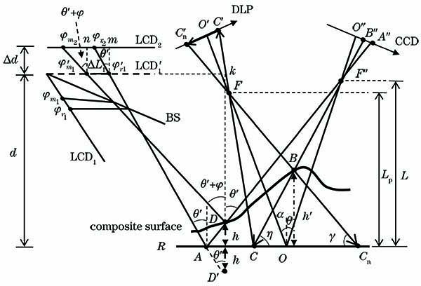
    Fig. 1. Schematic diagram of three-dimensional shape measurement of composite surface
    Geometry of the composite surface DPMD measurement
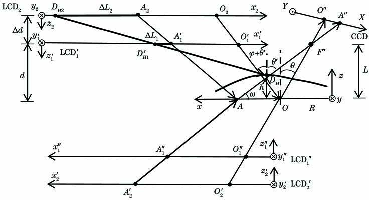
    Fig. 2. Geometry of the composite surface DPMD measurement
    Acquisition model
    Fig. 3. Acquisition model
    Specular fringe image obtained by simulation. (a) Reference surface; (b) measured surface; (c) reference surface collected by camera; (d) measured surface collected by camera
    Fig. 4. Specular fringe image obtained by simulation. (a) Reference surface; (b) measured surface; (c) reference surface collected by camera; (d) measured surface collected by camera
    Diffuse fringe image obtained by simulation. (a) Reference surface; (b) measured surface; (c) reference surface collected by camera; (d) measured surface collected by camera
    Fig. 5. Diffuse fringe image obtained by simulation. (a) Reference surface; (b) measured surface; (c) reference surface collected by camera; (d) measured surface collected by camera
    Height and error distribution of the composite surface. (a) Height; (b) error distribution
    Fig. 6. Height and error distribution of the composite surface. (a) Height; (b) error distribution
    Effect of system parameters on RMS. (a) Δd; (b) d; (c) P; (d) θ; (e) α
    Fig. 7. Effect of system parameters on RMS. (a) Δd; (b) d; (c) P; (d) θ; (e) α
    Measuring system of composite surface
    Fig. 8. Measuring system of composite surface
    Effect of actual measurement system parameters on RMS. (a) Δd; (b) d; (c) P; (d) θ; (e) α
    Fig. 9. Effect of actual measurement system parameters on RMS. (a) Δd; (b) d; (c) P; (d) θ; (e) α
    Three-dimensional reconstruction result of composite surface. (a) Tested composite steps; (b) fringe pattern of position1; (c) height map
    Fig. 10. Three-dimensional reconstruction result of composite surface. (a) Tested composite steps; (b) fringe pattern of position1; (c) height map
    StepActual distanceMeasured distanceAbsolute errorRMS
    1--23.00012.9740.0260.026
    2--33.99984.0240.0240.025
    3--45.00155.0310.0300.031
    4--55.49785.5240.0260.028
    5--66.49976.4720.0280.030
    Table 1. Experimental results on the composite stepunit: mm
    Zhinan Guo, Xiaohong Liu, Zonghua Zhang. Simulation and Verification of Three-Dimensional Shape Measurement Method for Composite Surface[J]. Laser & Optoelectronics Progress, 2020, 57(19): 191202
    Download Citation