We propose and demonstrate a novel scheme of semi-open-loop polarization control (SOL-PC), which controls the state of polarization (SOP) with high accuracy and uniform high speed. For any desired SOP, we first adjust the initial SOP using open-loop control (OLC) based on the matrix model of a three-unit piezoelectric polarization controller, and quickly move it close to the objective one. Then closed-loop control (CLC) is performed to reduce the error and reach precisely the desired SOP. The response time is three orders faster than that of the present closed-loop polarization control, while the average deviation is on par with it. Finally, the SOL-PC system is successfully applied to realize the suppression of the polarization mode dispersion (PMD) effect and reduce the first-order PMD to near zero. Due to its perfect performance, the SOL-PC energizes the present polarization control to pursue an ideal product that can meet the future requirements in ultrafast optical transmission and quantum communication.
Polarization control plays a crucial role in the fields of optical fiber-based high-speed optical transmission and quantum communication[1–7]. To guarantee the reliability of optical signals or quantum keys, the state of polarization (SOP) must be controlled effectively. Up to now, various polarization control schemes have been proposed, such as fiber bending[8] or squeezing[9], Faraday rotation[10,11], and photonic bandgap fiber[12]. Among them, piezoelectric polarization controllers (PPCs)[9] based on fiber squeezing are more practical and widely used because of their low power penalty, and are particularly suitable for optical fiber backbone systems. In a working PPC, squeezing will induce birefringence in the fiber, which causes a retardation between the two orthogonal modes perpendicular and parallel to the direction of pressure. Thus, the SOP varies with the squeezing pressure or the driving voltage (DV), which is the linearly amplified control voltage for the PPC. According to our previous work[9], the output SOP is a function of the DVs; thus, it can be controlled by applying the required voltage on each PPC unit.
To quickly produce accurate and stable polarization states, we present in this Letter a novel scheme of semi-open-loop polarization control (SOL-PC). We first establish a three-unit PPC system and obtain its matrix model for open-loop control (OLC) by which we can calculate the DVs for any desired output SOPs. Applying them to the PPC, we immediately get the SOP close to the objective one. If the difference between them is beyond the tolerant value, closed-loop control (CLC) is performed to reduce the error and achieve the precision objective SOP.
Our scheme combines both advantages of fast speed of OLC and precision of CLC, so we can generate an arbitrary SOP with a uniform fast speed, which has never been achieved by CLC alone. As we all know, it usually takes a much longer time to attain SOPs far away from the current one. In addition, to further reveal its great potential for applications in the suppression of polarization mode dispersion (PMD), we demonstrate the SOL-PC-based PMD suppression system.
Sign up for Chinese Optics Letters TOC. Get the latest issue of Chinese Optics Letters delivered right to you!Sign up now
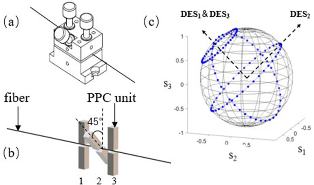
The core component of the PPC hardware is schematically shown in Fig. 1, where three PPC units oriented 45° from each other and controlled by the DVs, and the DVs working range is 0–150 V. Each PPC unit is made of a jaw and a piezoelectric actuator (PZT), where the optical fiber is placed between them. When applying voltage to the PZT, it stretches to squeeze the optical fiber. Due to the elastic-optic effect, the squeezing force of the PZT induces the stress birefringence in the optical fiber, which leads to the retardation and then changes the SOP. Since the PPC unit has a very low insertion loss and polarization dependent loss, its Mueller matrix can be expressed by a rotation matrix[9]where , , and the dynamic eigenstate of polarization (DES) of the PPC unit is [13].
Figure 1.Core component of the PPC hardware: (a) configuration, (b) principle, and (c) the SOP evolution on the Poincaré sphere when each PPC unit works.
The input and output Stokes vectors are related by , so the output SOP rotates around the DES when the DV changes. Figure 1(c) presents the evolution trajectories of three PPC units that were built for SOL-PC investigation.
In order to accurately obtain the DESs, we fit the SOP evolutionary traces by multiple linear regressions and calculate its normal vector, which is the DES exactly[9]. After such processing, we have and : ;: .
Then we further measure the rotation angle of the SOP at different DVs, and get the results shown in Fig. 2 by linear regression:
Figure 2.Relationship between the rotation angle of the SOP and the control voltage for PPC unit 1.
Inserting the above results into Eq. (1), we get of the first PPC unit. Using the same method, we obtain and of other two, and then the output SOP is determined by
Generally, the input SOP is fixed, so is only a function of the DVs (, , and ). Measuring three groups of and DVs, we can work out according to Eq. (3). For any desired , Eq. (3) is used to compute the required DVs. We apply them to the PPC units, and then get the approximate desired . In other words, this system does not need to measure the output SOP repeatedly and to adjust it through a complex feedback process as CLC does. Once the matrix is obtained in the initialization step, for any desired SOP, one just needs to calculate the required driving voltages by Eq. (3) and simply apply them to the PPC to get the desired SOP.
However, the output SOP deviation from the desired moves far away quickly when the number of PPC units increases, while the accuracy deteriorates due to the ferroelectric hysteresis of piezoelectric ceramics and environmental disturbances. To guarantee the accuracy of OLC, it is necessary to reduce the deviations. Thus we further apply the variable-step CLC to accurately achieve the desired SOP. The CLC process uses a polarization analyzer (PA, POD-201, General Photonics) for real-time monitoring of the output SOP from the PPC. When it deviates the required SOP, the system changes the driving voltage of the PPC step by step to decrease the deviation until the error is small enough or very close to the required SOP. Combining OLC with the CLC process, is called SOL-PC.
Figure 3 presents the flow chart of the SOL-PC scheme. The step means the output SOP goes forward one pace on the Poincaré sphere, which is a function of the DV increments and can be calculated by Eq. (3). Measuring the deviation between the current and the desired SOPs, if the initial step is larger than the deviation, reduce it to the half, then compare again, otherwise output the stepped DV. After several times of variable-step closed-loop feedback adjustment, the SOP meets the required accuracy and then the program stops; the entire SOL-PC process takes 3.2 ms.
To demonstrate the above SOL-PC scheme, we create the experimental system shown in Fig. 4. The 1550 nm laser passes through a mechanical polarization controller and goes into the PPC subsystem. The DV applied on the PPC is obtained by linearly amplifying the output from the digital to analog conversion (D/A) module controlled by a personal computer. The output SOP is monitored in real time by a polarization analyzer, measuring its Stokes vector and displaying it on the Poincaré sphere.
Figure 4.Experimental setup for investigation of the SOL-PC scheme. D/A: digital to analog conversion, A/D: analog to digital conversion
We first observe the evolution of the SOP when the SOL-PC scheme is performed. Figure 5 illustrates the whole evolution trajectory. It is clear that there are two sections that represent the OLC (blue line) and CLC (red circles) progress, respectively. Once the DVs are calculated by Eq. (3), they will be applied on the PPC, and the SOP jumps quickly along the blue trace to approximate the objective/desired SOP, which is completed within a few tens of microseconds. Then the deviation is reduced according to the flow chart in Fig. 3, and thus the SOP goes forward step by step, as shown by the red circles in Fig. 5, and finally reaches the desired SOP.
Figure 5.Evolution of the SOP on the Poincaré sphere when performing the SOL-PC.
Second, we choose randomly some SOPs as the desired SOPs (300 samples) and compare them with the experimental results. By statistical analysis, we find that the average deviation is 0.0283 rad on the Poincaré sphere. Table 1 shows some of the results.
No.
Desired SOP
Output SOP
Error (rad)
1
1.000,0.000,0.000
0.994,−0.104,0.017
0.0517
2
0.000,0.000,1.000
−0.040, −0.050,0.991
0.0293
3
0.312,0.156,0.937
0.315,0.132,0.948
0.0253
4
−0.662,0.181,0.723
−0.669,0.182,0.716
0.0105
5
0.082, −0.879, −0.468
0.044, −0.888, −0.455
0.0146
Table 1. Error Analysis Results of the SOL-PC Scheme
Moreover, we investigate the differences of the speed and error parameters among CLC, OLC, and SOL-PC, and the results show that CLC has the lowest response speed with the least error, while OLC is just contrary and has the highest speed with the largest error. However, our SOL-PC has a fast speed close to OLC, and less error on the bar of CLC, while they are the most uniform among these schemes. Some typical results are given in Table 2.
So far we have demonstrated the remarkable advantages of the SOL-PC scheme. It can greatly increase the response speed up to 3 orders of magnitude compared with the widely-used CLC, while it is uniform for any desired SOP that cannot be realized by the CLC.
The PMD effect has become one of the key obstacles that limit the speed of fiber transmission systems[14,15]. Considering the feasibility and high performance of the SOL-PC, we further reveal its great potential in the suppression of the first-order PMD effect. The experimental setup is schematically shown in Fig. 6.
In our experiment, the differential group delay (DGD) unit is a 3 m polarization-maintained fiber (PMF). The wavelength range of the tunable laser (TSL210, Santec) is from 1530 to 1610 nm. When changing the laser wavelength continuously, the output SOP goes along nearly a round circle on the Poincaré sphere, as shown in Fig. 7(a). That is the well-known PMD. To eliminate it, we make the PPC work with the SOL-PC scheme. Setting the principal states of polarization (PSP) as the desired SOP, the dispersed blue circle quickly focuses into a small point [Fig. 7(b)], which means the SOP no longer changes with the wavelength, namely, the PMD effect is well suppressed.
Figure 7.Evolution of the SOP on the Poincaré sphere for 3 m PMF as the wavelength varies (a) before and (b) after PMD suppression.
To further confirm the validity of the above result, we use the fixed-analyzer technique to measure the PMD before and after suppressing[16]. The first-order PMD or DGD is calculated by where is the modulus coupling coefficient, is the number of extreme values in the wavelength window (), and is the speed of light.
We employ a wide-band light source (PMD440, LED light source, PerkinElmer Inc.) to replace the tunable laser in Fig. 6, and measure the optical spectrum of the output by a spectrum analyzer (AQ6317B, Ando) with a couple of polarizers, and obtain the result as presented in Fig. 8(a). According to Eq. (4), we determine that the DGD of the 3 m PMF is 2.44 ps. After suppressing, we get the optical spectrum shown in Fig. 8(b), where one can find that almost all of the extrema disappear, which means the DGD is close to zero, that is to say, the first-order PMD has been suppressed extremely with uniform high speed[17].
Figure 8.Measured optical spectrum by the fixed-analyzer technique (a) before and (b) after PMD suppression.
In summary, we have proposed a new scheme of the SOL-PC for accurate polarization control with uniform high speed. Experimental results show the response time is three orders of magnitude faster compared to the present CLP control while the average deviation is on the same level. Applying the SOL-PC system, we successfully perform the suppression of the PMD effect, and reduce the first-order PMD to approximately zero. Due to its unique advantages, we are convinced that the SOL-PC will stimulate the progress of present polarization control to give birth to a perfect product that will satisfy the future advanced requirements. Compared with commonly used techniques, its advantages are very prominent, but it has higher requirements for the hardware to solve the matrix shown in Eq. (3). In case the data processing speed does not meet the requirements, it may limit the speed of polarization control. With higher-speed hardware and data processing, D/A and A/D conversion modules can be increased much more, so its performance will be further improved.