
Jiajia Zhao, Ming Tang, Kyunghwan Oh, Zhenhua Feng, Can Zhao, Ruolin Liao, Songnian Fu, Perry Ping Shum, Deming Liu. Polarization-maintaining few mode fiber composed of a central circular-hole and an elliptical-ring core[J]. Photonics Research, 2017, 5(3): 261
- Photonics Research
- Vol. 5, Issue 3, 261 (2017)
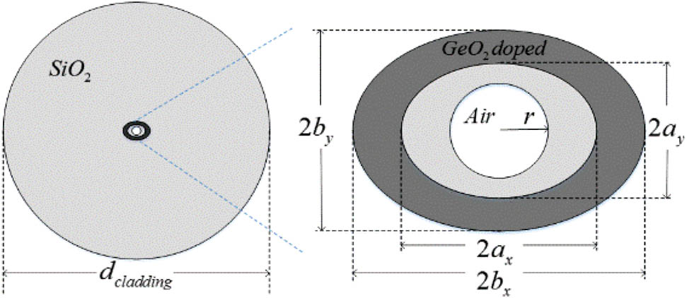
Fig. 1. Cross section of the proposed elliptical-ring core fiber with a central circular air hole. Key waveguide parameters are the cladding diameter d cladding r b x b y a x a y SiO 2 GeO 2 SiO 2
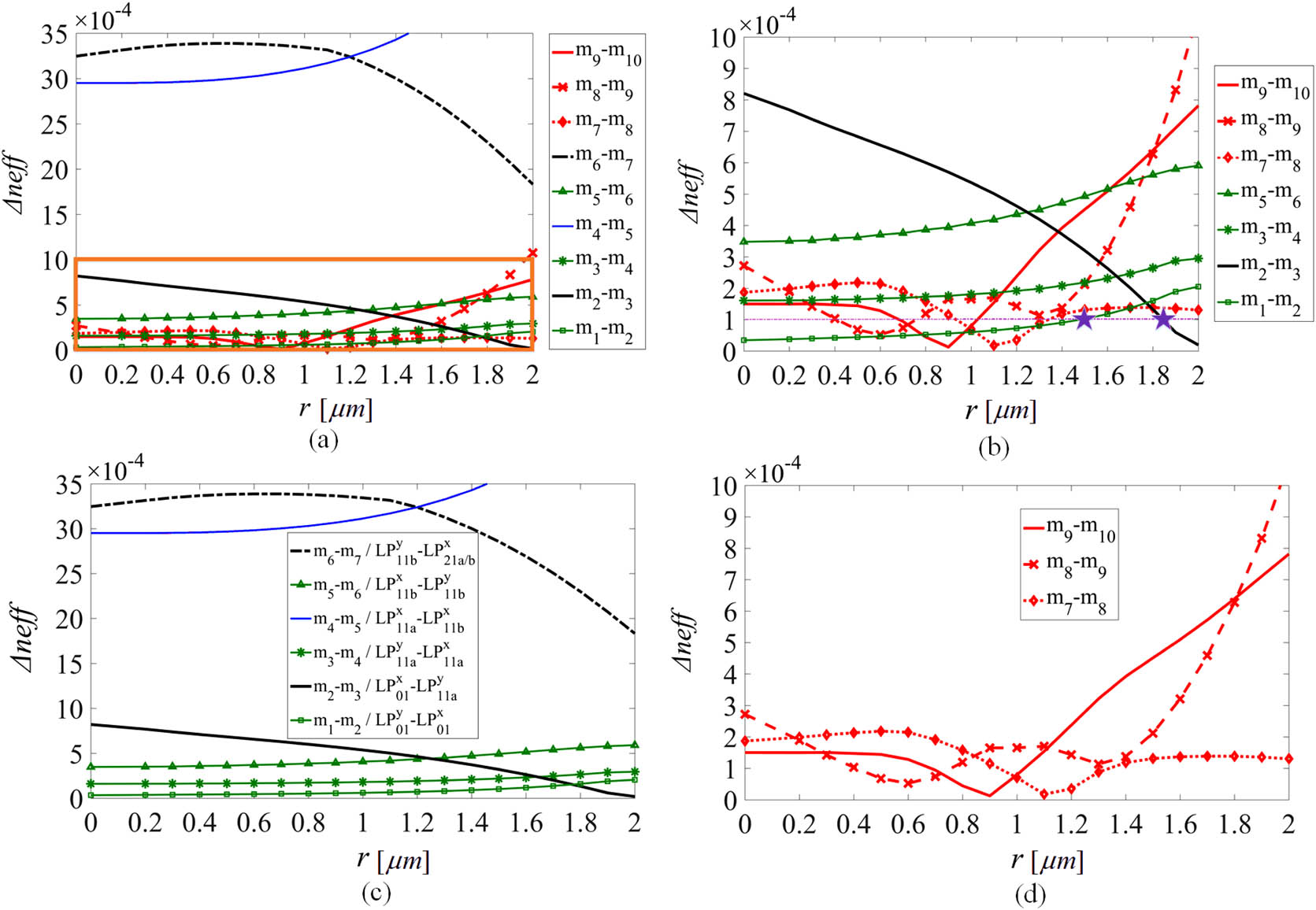
Fig. 2. In the situation that n ring = 1.478 n cladding = 1.444 d cladding = 125 μm η = 1.4 ρ = 0.67 b x = 5.06 μm λ = 1.55 μm Δ n eff r Δ n eff r Δ n eff r Δ n eff
Fig. 3. Transverse electrical fields, amplitudes, and directions of the vector modes at 1.55 μm for different sizes of air hole: (a) r = 0 μm r = 0.7 μm r = 0.9 μm r = 1.2 μm r = 1.7 μm
Fig. 4. (a) Effective refractive indices (n eff Δ n eff λ r = 1.7 μm n ring = 1.478 n cladding = 1.444 d cladding = 125 μm η = 1.4 ρ = 0.67 b x = 5.06 μm
Fig. 5. Transverse electrical fields, amplitudes and directions of the vector modes at 1.55 μm for the optimum air hole radius r = 1.8 μm
Fig. 6. (a) Effective refractive indices (n eff Δ n eff λ

Set citation alerts for the article
Please enter your email address
© Copyright 2018-2021 | Chinese Laser Press. All Rights Reserved 沪ICP备15018463号-20