Abstract
We propose a novel waveguide design of a polarization-maintaining few mode fiber (PM-FMF) supporting non-degenerate modes, utilizing a central circular air hole and a circumjacent elliptical-ring core. The structure endows a new degree of freedom to adjust the birefringence of all the guided modes, including the fundamental polarization mode. Numerical simulations demonstrate that, by optimizing the air hole and elliptical-ring core, a PM-FMF supporting 10 distinctive polarization modes has been achieved, and the effective index difference between the adjacent guided modes could be kept larger than over the whole band. The proposed fiber structure can be flexibly tailored to support an even larger number of modes in PM-FMF (14-mode PM-FMF has been demonstrated as an example), which can be readily applicable to a scalable mode division multiplexing system.1. INTRODUCTION
In the emerging era of big data and its applications, data amounts have been exploding, and the workload for optical networks and data centers (DCs) is approaching its physical limits [1]. It is reported that the current transmission system based on traditional single-mode fibers (SMFs) is rapidly reaching its ultimate capacity following the nonlinear Shannon limit [2]. In order to solve these imminent traffic bottlenecks, space-division multiplexing (SDM) transmissions have been recently intensively investigated as a viable measure [3]. The multicore fiber (MCF) [4–6], as one of the spatial multiplexing techniques, is the most straightforward solution in SDM. However, there are a great deal of technical challenges in the design and manufacture of high-core-count, low-loss, and low-crosstalk MCF. It is increasingly challenging to couple signals in and out of each core because the cores have to be closely packed in a scalable MCF [7]. The few mode fiber (FMF) [8–10] acts as another practical avenue in SDM, due to its mass-fabricated capability and low loss connectivity with conventional SMFs. The crosstalk among propagation modes is being regarded as the most crucial issue in FMF data links. To solve this issue, two different methods have been proposed. One is using the multiple input multiple output (MIMO) digital signal processing (DSP) at the receiver to electronically recover the signals carried over guided modes [11]. The drawback of this technique is that the complexity of MIMO scales up nonlinearly with the number of modes, easily depleting the DSP capacity and its electric power consumption. The other method is using specially designed FMF with a large difference in the effective indices between the adjacent propagation modes to fundamentally suppress the mode coupling [12]. Previous experiments have proved that the crosstalk can be efficiently suppressed when the effective index difference is larger than [13]. The latter method would have a clear advantage in energy efficiency; therefore, it would be especially suitable for the short-reach transmission in the DCs. This is the motivation of our research to design FMF flexibly scalable with a high for guided modes.
Elliptical core fibers (ECFs) [14–16] have been widely used as a polarization maintaining fiber (PMF), provided an efficient form-birefringence in the guided modes. In ECF, the effective index difference between the adjacent LP modes can be made large by increasing the refractive index contrast between the core and the cladding. In recent years, attempts to use ECF as a transmission medium in mode division multiplexing (MDM) has been reported to increase the system capacity and the spectral efficiency. In 2012, a three-mode (, , and ) transmission over ECF without using MIMO technique was reported [13]. In 2015, the first few-mode SDM transmission of real-time 10 Gb/s Ethernet traffic without coherent detection or MIMO-DSP over a 0.5 km elliptical-core FMF was achieved [17]. However, prior reports have suffered from the scalability issue such that all the ECFs mentioned above guided only a few higher-order modes, which may limit its overall capacity. Although higher birefringence in solid core ECF is helpful to increase the differences among the effective indices of the guided modes, it also cuts off some higher-order modes. Therefore, there is usually a trade-off between the number of guided modes and the achievable effective index difference [18]. In December 2015, an 8-mode polarization-maintaining (PM)-FMF with an elliptical-ring core had been reported [18]. This design successfully avoided the trade-off, achieving the highest number of PM modes thus far. However, among the 10 guided vector modes, the two fundamental polarization modes were still degenerate; thus, the full spatial mode diversity has not yet been efficiently exploited. References [19,20] have shown that the birefringence of the elliptical solid core fiber can be increased by an order of magnitude by placing an elliptical air hole in the fiber core center. However, the control of ellipticity of the central air hole would be a great challenge in practical fabrication processes.
In this paper, we propose a new FMF structure that can fully exploit the polarization mode splitting by using a circular air hole in the center, which also will facilitate fabrication stability. The structure endows a new degree of freedom to adjust the birefringence of all the guided modes, including the fundamental polarization mode. Thorough vectorial mode analyses showed that the two fundamental polarization modes can be effectively separated, and the minimum of among the 10 guided modes is attainable over the whole band. We also confirmed potential scalability of this structure, such that proposed fiber structure also could be extended to 14-mode PM-FMF.
Sign up for Photonics Research TOC. Get the latest issue of Photonics Research delivered right to you!Sign up now
The rest of the paper is organized in three sections. In Section 2, the schematic topology of the proposed PM-FMF is presented. In Section 3, the impact of the air hole size on the and modes properties is investigated and analyzed in detail. Finally, a brief conclusion is given in Section 4.
2. SCHEMATIC TOPOLOGY
The cross section of the proposed 10-mode PM-FMF is shown in Fig. 1, which comprises a circular air hole in the center, a circumjacent elliptical-ring core, and a circular cladding. The background material is pure silica, and the ring core is -doped silica. Moreover, a number of parameters are used to describe the fiber geometric structure. denotes the cladding diameter and denotes the air hole radius. The outer radii of along the and axes are and , respectively, and the inner radii of elliptical ring are and . The ratio, , represents the ellipticity. is the ratio between and , .
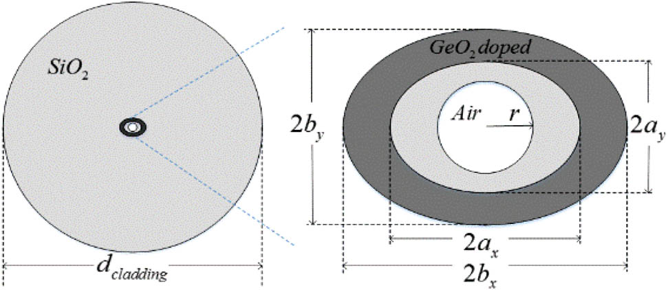
Figure 1.Cross section of the proposed elliptical-ring core fiber with a central circular air hole. Key waveguide parameters are the cladding diameter , the air hole radius , the major axes of the ring core, and , the minor axes, and , the cladding’s and core’s materials, and -doped .
Except for the air hole radius , all the other parameters of the fiber are set to be the same as the 8-mode PM-FMF with the optimal value as in Ref. [18], that is, , , , , , and . Here, numerical calculations were done with a finite element mode solver (COMSOL).
3. IMPACT OF AIR HOLE SIZE ON THE DIFFERENCE OF THE EFFECTIVE REFRACTIVE INDEX AND ANALYSIS
In this section, the main work is to find out the optimum value of the air hole size, so as to achieve the 10-mode PMF. The impact of the air hole size on the mode properties of the proposed fiber was carefully studied, and the detailed analysis also was performed.
Before setting out to do this work, we first noticed that the number of the guided modes decreases with the increase of the size of the air hole through the preliminary simulations. The reason may be that the air hole slightly impairs the effective refractive index of the ring core, thus leading some higher-order vector modes easily to leak out. To maintain the number of the vector modes supported by the fiber to be 10, either the ring width or the refractive index difference between the ring and the cladding should be increased. Here, we choose to enlarge from the reference value 1.474–1.478 to reach our target just by increasing the GeO2 doping rate from 20.95% to 23.75%.
Then, the next step is to search for the optimum value of the air hole radius . Figure 2(a) shows the between all adjacent guided modes as a function of air hole radius at the wavelength of 1550 nm with , , , , , and . In this case, the corresponding value of is 2.42 μm. Because the value of the air hole radius cannot be larger than that of , in our simulations, we increase the air hole radius from 0 μm to 2 μm with a step size of 0.1 μm. For convenience, these 10 guided modes from mode to mode are arranged by the order of their gradually decreased effective refractive index (). Another thing to note is that, in this figure, the lines with symbols are between orthogonal polarization of the same mode (modal birefringence), while the lines without symbols are the mode group separation.

Figure 2.In the situation that , , , , , , and : (a) the between the 10 adjacent modes as a function of the air hole radius ; (b) magnified image of the light orange rectangle in (a); (c) the between the first seven adjacent modes with increasing of ; (d) the between the last four adjacent modes with increasing of . Note that the lines with symbols are the between orthogonal polarization of the same mode (modal birefringence), while the lines without symbols are the mode group separation.
Figure 2(b) is the partial enlarged detail of Fig. 2(a), and it is easy to find that, if the air hole radius is within the range from 1.5 to 1.84 μm, the minimum among all guided modes can be larger than , which indicates its robustness to the air hole size. Especially, when , the minimum can reach to the highest value of . Thus, 10 guided modes can be completely separated by the method of adding a circular air hole of appropriate size in the fiber center.
Next, further research is carried out to explain how the air hole readjusts the of the 10 guided modes. In order to get a better view, Fig. 2(a) is divided into two parts, depicted in Figs. 2(c) and 2(d), respectively. The of the first seven adjacent lower-order modes are shown in Fig. 2(c), and the rest are shown in Fig. 2(d).
From Fig. 2(c), it is obvious that the between the non-degenerated LP modes decrease quickly as increases, as represented by the two black curves. On the contrary, the between these polarization modes gradually increase as increases, which are denoted by the three green curves. The blue curve represents the between the two degenerate modes of LP11 rather than two polarization modes, which also increases with . In summary, for the seven lower-order modes of the fiber, the air hole can slightly reduce the between non-degenerated modes and meanwhile enlarge the between degenerate modes, especially the between the two fundamental polarization modes, and .
On the other hand, the three red curves in Fig. 2(d) show different trends from that of the curves in Fig. 2(c). But they follow a common process of first dropping and then rising up. In particular, the curve of the between mode 8 and mode 9 experiences this process twice. In order to clarify the cause of the difference in Figs. 2(c) and 2(d), we perform a series of detailed analyses and find that the main reason is that the three red curves represent the between the four degenerate modes of , which can transform into each other as increases. During the transformation, there will be a situation that certain two modes of them become more and more alike to each other, resulting in the decrease of between these two modes. At last, the two modes will differ from each other, leading to their gradually increasing.
Figure 3 shows the process of transformation for all guided modes along with the increasing of air hole radius . It is clear that the order of the first six modes is fixed no matter how the air hole radius increases, but the order of the last four degenerate modes is constantly changing. For the situation without air holes, mode 7, mode 8, mode 9, and mode 10 represent , , , and , respectively. When air hole radius equals 0.7 μm, transformation between mode and mode is completed. It can be inferred that there must be a minimum value of between mode 8 and mode 9 before the value of , where the two modes are most similar to each other. This inference is verified by the result shown in Fig. 2(d), in which the first minimum between mode 8 and mode 9 is obtained at .
Figure 3.Transverse electrical fields, amplitudes, and directions of the vector modes at 1.55 μm for different sizes of air hole: (a) , (b) , (c) , (d) , and (e) .
As increases from 0.7 to 0.9 μm, the transformation between mode and mode is realized. Again, notice that is mode 9 and is mode 10. Thus, there is also a minimum between mode 9 and mode 10 near the value of , as illustrated by the curve of mode 9-mode 10 in Fig. 2(d). Similarly, there is a valley value of between mode 7 and mode 8 as well, especially, when , mode 8 and mode 9 perform a new round of interchange; thus, the curve of mode 9-mode 10 reaches another minimum value.
The modal wavelength dependency of the designed fiber over the whole band also is investigated when the air hole radius is fixed at the optimized value of 1.7 μm. The effective refractive indices and chromatic dispersions of all the 10 guided modes as a function of wavelength were calculated and are shown in Figs. 4(a) and 4(b), respectively. In the simulation, we include material dispersion effects in precise calculation of the effective indices of the guided modes, by using the mixed Sellmeier equation for the elliptical-ring core and the cladding [21]. The maximum chromatic dispersion for all guided modes is about over the band, indicating that the modal dispersions can be neglected when applied in short-reach optical interconnects. The minimal between all adjacent guided modes over the whole band is , as in Fig. 4(c).
Figure 4.(a) Effective refractive indices () of all guided modes. (b) Chromatic dispersions of all guided modes. (c) between all adjacent guided modes, as a function of the wavelength of , for the 10-mode PMF with , , , , , , and .
Furthermore, by increasing the elliptical ring width (here, only the parameter is increased from 5.06 to 5.46 μm, and all the other parameters are the same as that of the 10-mode FMF) and bringing in an air hole with the size from 1.7 to 1.88 μm, a 14-mode PMF also could be obtained. We choose the air hole size as the final design. Figure 5 is the transverse electrical fields of all the guided modes for the 14-mode PMF. Figures 6(a) and 6(b) are the effective refractive indices and chromatic dispersions of all the 14 guided modes as a function of the wavelength, respectively. It is obvious that the maximum chromatic dispersion for all guided modes is about over the C band. Besides, the between all the adjacent guided modes can be larger than over the whole band, as shown in Fig. 6(c). Thus, we believe that our proposed method is highly promising for the design of PMF with more modes, thus enabling the dense SDM transmission.
Figure 5.Transverse electrical fields, amplitudes and directions of the vector modes at 1.55 μm for the optimum air hole radius .
Figure 6.(a) Effective refractive indices () of all guided modes. (b) Chromatic dispersions of all guided modes. (c) between all adjacent guided modes, as a function of the wavelength of , for the 14-mode PMF.
For the fabrication of this kind of fiber, one possible way is to use the following steps to achieve it. First, a pure silica preform is prepared and cut to provide two flat surfaces. Second, the ring-shaped germanosilica core layers are deposited over the prepared preform by the conventional modified chemical vapor deposition process. Third, the two flat surfaces flow to form a circular shape at a high temperature, leaving behind an elliptical-ring germanosilica core. Fourth, a circular air hole is drilled in the preform center, and then the final preform is drawn to fiber. Though, for the elliptical-ring hollow core fiber, the high drawing temperature tends to seal the central air hole, but by careful control of the temperature and tension at the drawing process, the hole can be maintained and prone to have a circular shape due to the built-in positive pressure [20].
4. CONCLUSIONS
In conclusion, we proposed and numerically demonstrated a mode-number scalable PM-FMF by utilizing an elliptical-ring core FMF assisted with a central circular air hole. The impact of the air hole size on the and properties of all guided modes are thoroughly investigated. Theoretical results show that a 10 distinctive polarization mode FMF has been achieved, and the minimum among all guided modes can reach over the whole band. The maximum chromatic dispersion for all propagation modes is less than , not affecting the normal use of the fiber in the short-distance transmission. Additionally, a 14-mode PMF also was obtained by the same method proposed in the paper. We believe this method can be further applied to design PMF supporting more modes. Meanwhile, we hope the high performance of the 10-mode and 14-mode PMFs can be used as a promising transmission medium and play an important role in the future bandwidth intensive high-capacity DCs.
References
[1] L. Schares, B. Lee, F. Checconi, R. Budd, A. Rylyakov, N. Dupuis, F. Petrini, C. Schow, P. Fuentes, O. Mattes, C. Minkenberg. A throughput-optimized optical network for data-intensive computing. IEEE Micro, 34, 52-63(2014).
[2] R. J. Essiambre, G. Kramer, P. J. Winzer, G. J. Foschini, B. Goebel. Capacity limits of optical fiber networks. J. Lightwave Technol., 28, 662-701(2010).
[3] T. Mizuno, H. Takara, A. Sano, Y. Miyamoto. Dense space division multiplexed transmission systems using multi-core and multi-mode fiber. J. Lightwave Technol., 34, 582-592(2016).
[4] J. Tu, K. Saitoh, M. Koshiba, K. Takenaga, S. Matsuo. Design and analysis of large-effective-area heterogeneous trench-assisted multi-core fiber. Opt. Express, 20, 15157-15170(2012).
[5] B. J. Puttnam, R. S. Luis, W. Klaus, J. Sakaguchi, J. M. D. Mendinueta, Y. Awaji, N. Wada, Y. Tamura, T. Hayashi, M. Hirano, J. Marciante. 2.15 Pb/s transmission using a 22 core homogeneous single-mode multi-core fiber and wideband optical comb. European Conference on Optical Communication (ECOC), PDP3–1(2015).
[6] J. Sakaguchi, B. J. Puttnam, W. Klaus, J. M. D. Mendinueta, Y. Awaji, N. Wada, A. Kanno, T. Kawanishi. Large-capacity transmission over a 19-core fiber. Optical Fiber Communication Conference, OW1I.3(2013).
[7] B. Zhu, T. F. Taunay, M. Fishteyn, X. Liu, S. Chandrasekhar, M. F. Yan, J. M. Fini, E. M. Monberg, F. V. Dimarcello. 112-Tb/s Space-division multiplexed DWDM transmission with 14-b/s/Hz aggregate spectral efficiency over a 76.8-km seven-core fiber. Opt. Express, 19, 16665-16671(2011).
[8] F. Ferreira, D. Fonseca, H. Silva. Design of few-mode fibers with arbitrary and flattened differential mode delay. IEEE Photon. Technol. Lett., 25, 438-441(2013).
[9] F. M. Ferreira, D. Fonseca, H. J. A. da Silva. Design of few-mode fibers with M-modes and low differential node delay. J. Lightwave Technol., 32, 353-360(2014).
[10] S. Chebaane, H. Seleem, H. Fathallah, M. Machhout. Design tradeoffs of few-mode step index fiber for next generation mode division multiplexing optical networks. International Conference on Information and Communication Technology Research (ICTRC), 262-265(2015).
[11] R. Ryf, S. Randel, A. H. Gnauck, C. Bolle, A. Sierra, S. Mumtaz, M. Esmaeelpour, E. C. Burrows, R. J. Essiambre, P. J. Winzer, D. M. Peckham, A. H. McCurdy, J. R. Lingle. Mode-division multiplexing over 96 km of few-mode fiber using coherent 6 × 6 MIMO processing. J. Lightwave Technol., 30, 521-531(2012).
[12] M. Kasahara, K. Saitoh, T. Sakamoto, N. Hanzawa, T. Matsui, K. Tsujikawa, F. Yamamoto, M. Koshiba. Design of few-mode fibers for mode-division multiplexing transmission. IEEE Photon. J., 5, 7201207(2013).
[13] N. Riesen, J. D. Love, J. W. Arkwright. Few-mode elliptical-core fiber data transmission. IEEE Photon. Technol. Lett., 24, 344-346(2012).
[14] M. Park, L. Schenato, L. Palmieri, S. Lee, A. Galtarossa, K. Oh. Dual-core elliptical hollow optical fiber with linearly wavelength-decreasing birefringence. European Conference on Optical Communication (ECOC), P1.04(2010).
[15] I. K. Hwang, Y. H. Lee, K. Oh, D. N. Payne. High birefringence in elliptical hollow optical fiber. Opt. Express, 12, 1916-1923(2004).
[16] Y. Yue, G. kai, Z. Wang, Y. Lu, C. Zhang, T. Sun, Y. Li, L. Jin, J. Liu, Y. Liu, S. Yuan, X. Dong. Highly birefringent elliptical-hole photonic crystal fiber with two big circular air holes adjacent to the core. IEEE Photon. Technol. Lett., 18, 2638-2640(2006).
[17] E. Ip, G. Milione, M. J. Li, N. Cvijetic, K. Kanonakis, J. Stone, G. Peng, X. Prieto, C. Montero, V. Moreno, J. Liñares. SDM transmission of real-time 10GbE traffic using commercial SFP + transceivers over 0.5km elliptical-core few-mode fiber. Opt. Express, 23, 17120-17126(2015).
[18] L. Wang, S. LaRochelle. Design of eight-mode polarization-maintaining few-mode fiber for multiple-input multiple-output-free spatial division multiplexing. Opt. Lett., 40, 5846-5849(2015).
[19] M. J. Li, X. Chen, D. A. Nolan, G. E. Berkey, J. Wang, W. A. Wood, L. A. Zenteno. High bandwidth single polarization fiber with elliptical central air hole. J. Lightwave Technol., 23, 3454-3460(2005).
[20] Y. Jung, S. R. Han, S. Kim, U. C. Paek, K. Oh. Versatile control of geometric birefringence in elliptical hollow optical fiber. Opt. Lett., 31, 2681-2683(2006).
[21] S. Lee, J. Park, Y. Jeong, H. Jung, K. Oh. Guided wave analysis of hollow optical fiber for mode-coupling device applications. J. Lightwave Technol., 27, 4919-4926(2009).


