• Advanced Photonics
  • Vol. 2, Issue 6, 066005 (2020)
Pouya Rajaeipour*, Kaustubh Banerjee, Alex Dorn, Hans Zappe, and Çağlar Ataman
Author Affiliations
  • University of Freiburg, Gisela and Erwin Sick Laboratory for Micro-Optics, Department of Microsystems Engineering, Freiburg, Germany
  • show less
    DOI: 10.1117/1.AP.2.6.066005 Cite this Article Set citation alerts
    Pouya Rajaeipour, Kaustubh Banerjee, Alex Dorn, Hans Zappe, Çağlar Ataman. Cascading optofluidic phase modulators for performance enhancement in refractive adaptive optics[J]. Advanced Photonics, 2020, 2(6): 066005 Copy Citation Text show less
    (a) The conventional usage of two reflective elements for AO versus (b) the cascaded configuration of two refractive DPPs. DM: deformable mirror.
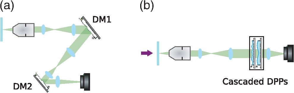
    Fig. 1. (a) The conventional usage of two reflective elements for AO versus (b) the cascaded configuration of two refractive DPPs. DM: deformable mirror.
    (a) Schematics of the employed DPPs and their proposed cascaded configuration. DPP1 has 25 keystone-patterned electrodes that are distributed within an area of 12 mm in diameter, and DPP2 has 37 hexagonally patterned electrodes that can be circumscribed inside a circle of 12 mm in diameter. (b) Top and side views of the fabricated DPPs. (c) Stacked DPPs in their 60-mm cage system compatible packaging and electrical interfacing.
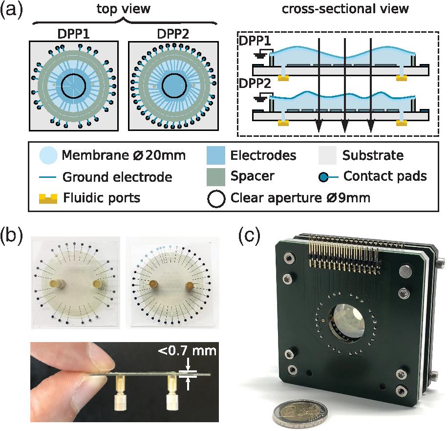
    Fig. 2. (a) Schematics of the employed DPPs and their proposed cascaded configuration. DPP1 has 25 keystone-patterned electrodes that are distributed within an area of 12 mm in diameter, and DPP2 has 37 hexagonally patterned electrodes that can be circumscribed inside a circle of 12 mm in diameter. (b) Top and side views of the fabricated DPPs. (c) Stacked DPPs in their 60-mm cage system compatible packaging and electrical interfacing.
    Open-loop control method for simultaneous control of cascaded DPPs. (a) Control flowchart and (b) visualization of different steps of replicating a target wavefront.
    Fig. 3. Open-loop control method for simultaneous control of cascaded DPPs. (a) Control flowchart and (b) visualization of different steps of replicating a target wavefront.
    Experimental evaluation of the introduced open-loop control for replicating two example wavefronts using DPP1 and DPP2. A target wavefront is chosen and the control signals of the DPP1 are calculated. The keystone patterns on each plot show the voltage distribution of the DPP1. These control signals are used to estimate the DPP1 response by its response model. The two wavefront profiles on each plot compare the estimated response from experimental measurements. Bar plots compare the Zernike decomposition of the target and reproduced wavefronts at each step of the control algorithm depicted in Fig. 3(a). Interferometric measurements are performed using a HeNe laser (λ=632 nm).
    Fig. 4. Experimental evaluation of the introduced open-loop control for replicating two example wavefronts using DPP1 and DPP2. A target wavefront is chosen and the control signals of the DPP1 are calculated. The keystone patterns on each plot show the voltage distribution of the DPP1. These control signals are used to estimate the DPP1 response by its response model. The two wavefront profiles on each plot compare the estimated response from experimental measurements. Bar plots compare the Zernike decomposition of the target and reproduced wavefronts at each step of the control algorithm depicted in Fig. 3(a). Interferometric measurements are performed using a HeNe laser (λ=632  nm).
    Experimental results for replicating up to the sixth radial order of Zernike modes. (a) Comparing the maximum achievable mode amplitude and their corresponding purity [see Eq. (6)] using DPP1 and DPP2 individually (depicted by green squares and blue triangles, respectively), and simultaneously with the cascaded configuration and the proposed control method (red circles). (b) Overview of the wavefront profiles of the replicated Zernike modes using the cascaded DPPs. The top-left figure shows the overlay of DPP1 and DPP2 electrode patterns. Interferometric measurements are performed using a HeNe laser (λ=632 nm).
    Fig. 5. Experimental results for replicating up to the sixth radial order of Zernike modes. (a) Comparing the maximum achievable mode amplitude and their corresponding purity [see Eq. (6)] using DPP1 and DPP2 individually (depicted by green squares and blue triangles, respectively), and simultaneously with the cascaded configuration and the proposed control method (red circles). (b) Overview of the wavefront profiles of the replicated Zernike modes using the cascaded DPPs. The top-left figure shows the overlay of DPP1 and DPP2 electrode patterns. Interferometric measurements are performed using a HeNe laser (λ=632  nm).
    (a) Schematic layout of the developed AO microscope. P, pupil plane; O, object; OL, objective lens; EF, emission filter; and I, image. (b) Detailed view of the ray-tracing simulation model at the location of cascaded DPPs each having a 7-mm offset from the conjugated pupil plane. Simulation results depicting the amplitudes of the Zernike modes with respect to field positions for (c) the ideal case of having both DPPs directly at the pupil plane, (d) only DPP1 actuated while being positioned 7 mm behind the pupil plane, (e) only DPP2 actuated while being positioned 7 mm in front of the pupil plane, and (f) DPP1 and DPP2 actuated simultaneously at their offset-position. (g) Overview of the fully refractive AO microscope with the integrated cascaded DPPs.
    Fig. 6. (a) Schematic layout of the developed AO microscope. P, pupil plane; O, object; OL, objective lens; EF, emission filter; and I, image. (b) Detailed view of the ray-tracing simulation model at the location of cascaded DPPs each having a 7-mm offset from the conjugated pupil plane. Simulation results depicting the amplitudes of the Zernike modes with respect to field positions for (c) the ideal case of having both DPPs directly at the pupil plane, (d) only DPP1 actuated while being positioned 7 mm behind the pupil plane, (e) only DPP2 actuated while being positioned 7 mm in front of the pupil plane, and (f) DPP1 and DPP2 actuated simultaneously at their offset-position. (g) Overview of the fully refractive AO microscope with the integrated cascaded DPPs.
    Imaging fluorescent micro-beads (Ø=1 μm) behind an aberrating phase plate that mimics specimen-induced aberrations while deep tissue imaging. (a) Aberrated frames, corrected frames using (b) a single DPP and (c) the cascaded configuration, (d) quality score of the obtained frames after each iteration of the aberration estimation algorithm, and (e) the estimated wavefront error by executing the sensorless aberration estimation algorithm using stacked DPPs. Length of the scale bars is 20 μm.
    Fig. 7. Imaging fluorescent micro-beads (Ø=1  μm) behind an aberrating phase plate that mimics specimen-induced aberrations while deep tissue imaging. (a) Aberrated frames, corrected frames using (b) a single DPP and (c) the cascaded configuration, (d) quality score of the obtained frames after each iteration of the aberration estimation algorithm, and (e) the estimated wavefront error by executing the sensorless aberration estimation algorithm using stacked DPPs. Length of the scale bars is 20  μm.
    Iteration No.Correcting modes (Zernike index)M1M2Bias amplitude
    13, 5, 7, 81%5%25 rad
    23, 5, 7, 81%5%15 rad
    33, 5, 7, 8, 121%10%10 rad
    43, 5 to 141%35%5 rad
    53, 5 to 141%35%5 rad
    63, 5 to 141%35%1 rad
    73, 5 to 201%80%1 rad
    Table 1. Parameters of the sensorless aberration estimation algorithm employed for the experiments presented in this paper. M1 and M2 depict the minimum and maximum of the normalized spatial frequencies, respectively, to be used for calculation of the MF using Eq. (7).
    Pouya Rajaeipour, Kaustubh Banerjee, Alex Dorn, Hans Zappe, Çağlar Ataman. Cascading optofluidic phase modulators for performance enhancement in refractive adaptive optics[J]. Advanced Photonics, 2020, 2(6): 066005
    Download Citation