
Junxiang Huang, Tao Fu, Haiou Li, Zhaoyu Shou, Xi Gao. A reconfigurable terahertz polarization converter based on metal–graphene hybrid metasurface[J]. Chinese Optics Letters, 2020, 18(1): 013102
- Chinese Optics Letters
- Vol. 18, Issue 1, 013102 (2020)
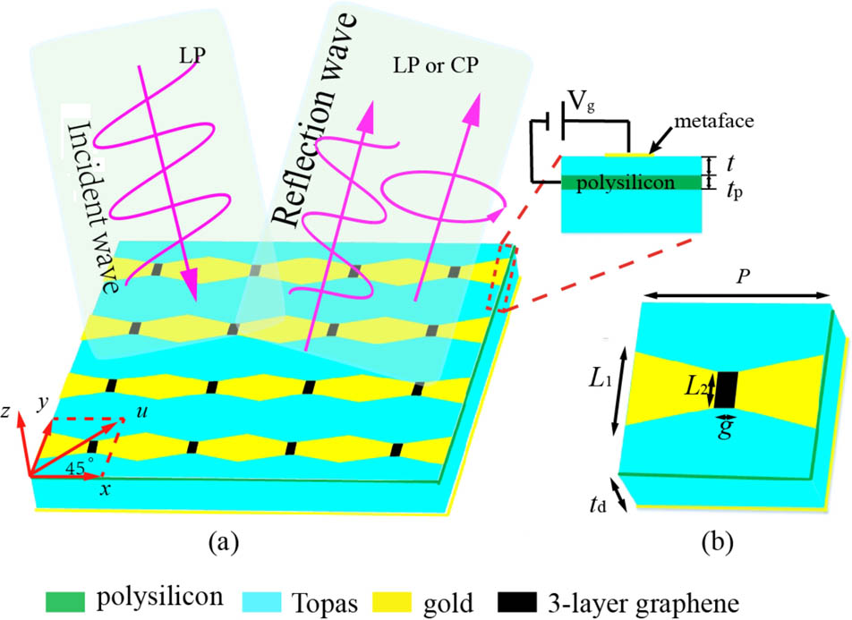
Fig. 1. (a) Schematic diagram of the proposed device. (b) Unit cell of the polarizer.
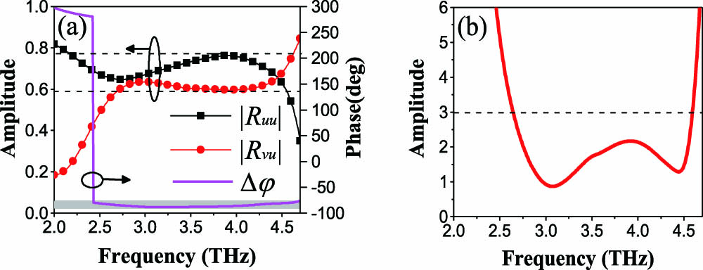
Fig. 2. Simulated
Fig. 3. In case of
Fig. 4. AR of the reflection wave plotted as a function of
Fig. 5. In case of
Fig. 6. Device performance varied with
Fig. 7. (a), (b) The equivalent circuits of the metasurface for
Fig. 8. (a) Resistance and (b) inductance for different
Fig. 9. Simulated
|
Table 1. Optimized Values of the Circuit Elements for N=3

Set citation alerts for the article
Please enter your email address
© Copyright 2018-2021 | Chinese Laser Press. All Rights Reserved 沪ICP备15018463号-20