Junxiang Huang, Tao Fu, Haiou Li, Zhaoyu Shou, Xi Gao, "A reconfigurable terahertz polarization converter based on metal–graphene hybrid metasurface," Chin. Opt. Lett. 18, 013102 (2020)
Copy Citation Text
A metal–graphene hybrid metasurface polarization converter is designed in this Letter. The unit cell of the hybrid metasurface is composed of a butterfly-shaped structure whose branches are connected by multi-layer graphene sheets. The proposed device can be reconfigured from linear-to-circular polarization to cross-polarization by changing the Fermi energy of graphene. The simulation results show that for three-layer graphene, the device acts as a linear-to-circular polarization converter when EF = 0 eV and switches to a cross-polarization converter when EF = 0.5 eV. Compared with single-layer graphene, the device with three-layer graphene can maintain the cross-polarization conversion performance under low Fermi energy. Furthermore, two equivalent circuits in the x and y directions are developed to understand the working mechanism of the device.
In recent years, the metasurface[1] provides a novel way to control the polarization state of electromagnetic (EM) waves by reasonably designing its unit cells. Especially, the metasurface-based polarization devices have the main advantages of ultrathin thickness and simple configuration. Based on these fascinating characteristics, metasurface-based polarizers[2–12] are becoming popular to control the polarization state of the EM wave. Ye et al. designed a polarization converter[3] using a chiral structure, which can effectively realize cross-polarization conversion in a narrow band. To achieve broadband polarization conversion performance, a polarizer based on a double V-shaped metasurface was proposed[4], which can convert a -polarized wave to an -polarized wave with relative bandwidth up to 79%. More recently, some metasurface-based polarized devices have been proposed in the terahertz (THz) regime. For example, Sun et al. designed a polarizer that can efficiently convert a -polarized incident wave into an -polarized transmission wave in the frequency range of 0.25 THz to 0.65 THz[13]. The aforementioned polarization devices present many good properties, such as broadband and high polarization conversion efficiency, but their functionalities are fixed. In practical applications, however, reconfigurable polarization converters are more desirable. In order to realize reconfigurable functionalities, some voltage-controlled elements or active materials, such as varactor diodes or graphene, are integrated into metaparticles[14–23]. Especially for graphene[24], it has obvious advantages to realize a tunable device in the THz regime due to its two-dimensional structure and voltage-controlled conductivity. Based on these properties, some graphene-based devices[15–17] including polarization converters[18–21] have been developed to tune their operation frequencies or reconfigure their functionalities. Cheng et al. proposed a dynamically tunable cross-polarization converter based on an L-shaped graphene array[18]. By increasing the Fermi energy of graphene, the operation wavelength of the device shows a blue shift. In Ref. [19], a tunable cross-polarization converter was designed based on a metasurface formed by periodically etching H-shaped holes on a graphene sheet. Although the operation frequencies of these devices were able to be tuned by the Fermi energy of graphene, their tunable bandwidth is limited. To solve this problem, a novel graphene-based polarization converter was proposed in Ref. [20]. In this device, the metal ground was placed by a multi-layer graphene sheet, except that the metasurface was constructed by a single-layer graphene sheet. The multi-layer graphene[25] ground can effectively modulate the phase of its reflected wave by Fermi energy, which provided a constructive interference condition at the interface between free space and metasurface in a broad bandwidth, thus significantly broadening the tunable bandwidth of the device. On the other hand, multi-functional polarization converters can be realized by using a hybrid metasurface that is composed of metal and graphene. In our prior work[21], a reconfigurable polarization converter was proposed to switch its functionality among linear-to-linear, linear-to-circular, and linear-to-elliptical polarization conversion. In this device, two single-layer graphene wires spaced by a thin silicon dioxide layer were employed, which need a high bias voltage to realize tunable functionality, and, furthermore, it is difficult to fabricate samples.
In this Letter, we propose a reconfigurable polarization converter based on a novel metal–graphene hybrid metasurface. The unit cell of the hybrid metasurface is composed of a butterfly-shaped structure whose branches are connected by a multi-layer graphene sheet. By changing the Fermi energy of graphene, the EM response in the -direction is tunable, which leads to a reconfigurable polarization conversion functionality. Meanwhile, the tunable polarization conversion functionality can be realized under low Fermi energy of graphene by employing multi-layer graphene. Additionally, two equivalent circuits along the - and -directions are developed to understand the polarization conversion mechanism.
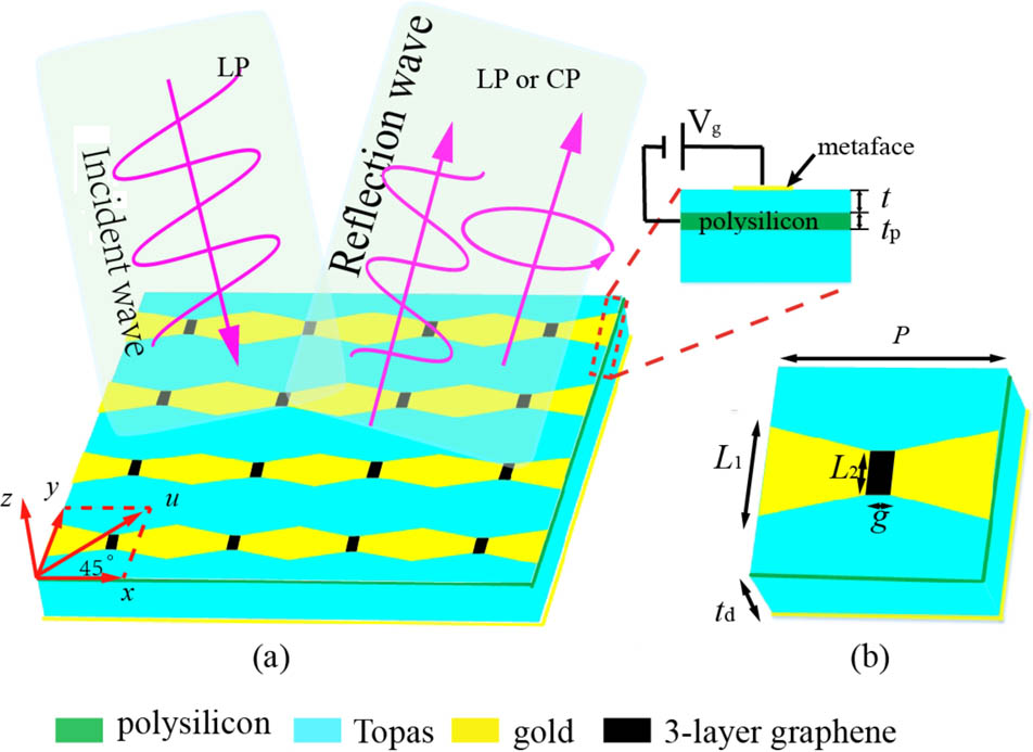
Figure 1(a) presents the schematic configuration of the proposed polarization converter whose unit cell [see Fig. 1(b)] is composed of a butterfly-shaped structure, a dielectric substrate, a gating layer, and a ground plate. The two branches of the butterfly-shaped structure are connected by a single- or multi-layer graphene sheet. A polyethylene cyclic olefin copolymer (Topas) with permittivity is employed as the dielectric substrate. In addition, a thin polysilicon () is used as a gating layer, which is placed beneath the metasurface to load bias voltage (Vg) for the graphene sheet. The designed parameters of the unit cell are μ, μ, μ, μ, μ, and μ. The thickness of polysilicon is μ.
Sign up for Chinese Optics Letters TOC. Get the latest issue of Chinese Optics Letters delivered right to you!Sign up now
Figure 1.(a) Schematic diagram of the proposed device. (b) Unit cell of the polarizer.
With the help of commercial software, CST Microwave Studio 2016, the reflective characteristics of the device are studied. In simulation, a unit cell with periodic boundary conditions along the and directions is used. The device is illuminated with a linearly polarized wave with the electric field vector tilted 45° relative to both and directions. Simultaneously, we first define the reflection coefficients and to denote co- and cross-polarization reflection coefficients for the -polarized incident wave. It is well known that when and the phase difference , the reflection wave is a circularly polarized wave. However, when , the reflected wave is a linearly polarized wave.
Figure 2 presents the simulated and of the device with three-layer graphene when . As shown in Fig. 2(a), the is approximately equal to in the frequency range of 2.5 THz to 4.7 THz. Moreover, their phase difference is . It means that the device converts the linearly polarized incident waves to a circularly polarized reflection wave. To further investigate the circular polarization property of the reflected wave, we analyze its axial ration (AR), as shown in Fig. 2(b). It is observed that the AR is less than 3 dB from 2.5 THz to 4.7 THz, with a relative bandwidth of 41%, demonstrating the excellent circular polarization conversion performance of the proposed device.
Figure 2.Simulated , , and AR for and . (a) The amplitude ( and ) and phase difference () of the reflection coefficient. (b) The AR of the reflected wave.
Figure 3 presents the reflection characteristics for , from which we see that and in the frequency range from 2.5 THz to 3.8 THz. It means that the device acts as a cross-polarization converter that rotates a -polarized wave into a -polarized wave. Moreover, we further observe that the polarization conversion ratio (PCR) is larger than 0.9 in the band from 2.5 THz to 3.8 THz, implying a good performance of linear polarization conversion. Figure 4 plots the AR as a function of , which shows that, in the frequency range of 2.5 THz to 4.0 THz, the AR is changed from less than 3 dB to greater than 10 dB when is increased from 0 eV to 0.5 eV, indicating that the device function is switched from a linear-to-circular polarization converter to a cross-polarization converter.
Figure 3.In case of and , the amplitude of the reflection coefficient ( and ) and the PCR for linear polarization conversion.
In addition, we study the influence of graphene layer () on the performance of the device for . Figure 5 illustrates the reflection coefficients ( and ) varied with . In the interesting frequency range from 3 THz to 4.7 THz, the amplitude and the phase difference of and are slightly changed with increasing from 1 to 3 [see Fig. 5(a)]. It implies that the number of the graphene layer () has little influence on device performance when . In order to further understand the polarization state of the reflected wave, Stokes parameters are introduced as
Figure 5.In case of , the simulated , , and ellipticity for . (a) The amplitudes and the phase difference of and . (b) The ellipticity.
Then, the ellipticity of the reflective wave is defined as . When , the reflected wave is a right-handed circularly polarized wave; whereas, when , the reflected wave is a left-handed circularly polarized wave. As can be seen from Fig. 5(b), the ellipticity of the reflective wave is approximately equal to in the interesting frequency band, which proves that in case of , the reflected wave is a left-handed circularly polarized wave, regardless of the value of .
When is higher than 0 eV, the EM response of the proposed device is illustrated in Fig. 6. It is observed that the device performance improves greatly with the increase of . For , the amplitude of is much larger than that of in the interesting frequency band [see Fig. 6(a)], which makes the PCRs for significantly improved [see Fig. 6(b)]. Moreover, for the same device functionality, the of graphene decreases with the increasing of . For example, to obtain linear polarization conversion, at , at , and at . According to Ref. [26], the Fermi energy of graphene can be calculated by the formula , where and are the permittivity of polysilicon and vacuum, respectively, and are electron charge and reduced Planck’s constant, and and are bias voltage and the Fermi velocity of graphene. Additionally, we set these parameters as , , , , and . Then, we plot the as a function of , as illustrated in Fig. 6(c). It is observed that when changes from 0.8 eV to 0.5 eV, the bias voltage decreases from 299 V to 117 V, implying that the bias voltage of graphene can be significantly reduced by increasing the number of graphene layers. Combining with Figs. 6(b) and 6(c), we deduce that the proposed device can realize the linear polarization function under lower bias voltage of graphene if we increase the value of .
Figure 6.Device performance varied with . (a) The and . (b) The PCR. (c) The relationship between and .
Here, equivalent circuits are extracted to further understand the mechanism of polarization conversion. When a -polarized wave (see the inset in Fig. 3) is employed to excite the device, its electric field can be decomposed into and components. Due to the anisotropy of the metasurface, there are different circuit models along the and directions. So, as long as the equivalent circuits along the and directions are extracted, we can get the physical insight of polarization conversion by analyzing the equivalent circuits. For the -polarized incident wave, the metal patches are regarded as an equivalent inductance , and the gaps between adjacent metal patches are equal to a capacitance [27]. The graphene sheets connecting the butterfly-shaped metal patches are regarded as impedance , which is parallel to the equivalent capacitance , as illustrated in Fig. 7(a). Similarly, the equivalent circuit along the direction can also be extracted, as shown in Fig. 7(b). The air and substrate layer are considered as the transmission lines with the characteristic impedance of and , respectively, and then the transmission lines are shortened at the metal ground. Finally, the whole equivalent circuits along the and directions are obtained, as presented in Figs. 7(c) and 7(d). Based on the two equivalent circuits, their input impedances in the and directions are denoted as where the inductance ( or ) and capacitance ( or ) formed by periodic patches are estimated by the following equations[28]: where and are the permittivity and permeability of free space, respectively, is the effective permittivity of the metasurface, is the width of the metal patch, is the gap between two adjacent metal patches, and is the period of the metasurface. On the other hand, the impedance of the graphene sheet can be calculated from the following equation[29]: where and are defined in Fig. 1, is the operation frequency, and and are the thickness and relative dielectric constant of graphene. Based on Eq. (9), we obtain the graphene impedance varying as the function of frequency for different and , as illustrated in Fig. 8. For , the graphene presents high impedance, including high resistance and high inductance. Furthermore, the impedance is decreased with the increasing of . In this case, the device acts as a circular polarization converter, but the number of graphene layers has some influence on the performance of the device (see Fig. 5) due to their different impedance characteristics. For and , however, the two- and three-layer graphene have almost equivalent resistance and inductance that are close to zero, which results in the same linear polarization conversion functionality (see Fig. 6). From Fig. 8, we conclude that the impedance of graphene is controlled by and . By choosing an adaptive number of graphene layers such as , the proposed device can realize reconfigurable polarization conversion under low Fermi energy () of graphene.
Figure 7.(a), (b) The equivalent circuits of the metasurface for - and -polarized incident waves. (c), (d) The equivalent circuit models along the and directions.
The initial values of and are estimated by using Eqs. (7) and (8), and the impedance of graphene under different is obtained from Eq. (9). Then, according to the optimization goal of , the equivalent circuit parameters are optimized by using the software of MATLAB, as shown in Table 1. Based on these optimized circuit elements, the parameters of the two equivalent circuits are calculated and compared with the reflection coefficients ( and ) obtained from CST, as shown in Figs. 9(a) and 9(b). We see that for and 0.5 eV, the parameters obtained from the equivalent circuits are coincident with the reflection coefficients and simulated by using CST, demonstrating the availability of the extracted equivalent circuit. By comparing Figs. 9(a) and 9(b), we find that when the of graphene is changed from 0 eV to 0.5 eV, the reflection coefficients ( and ) for the -polarized incident wave are different from , but the reflection coefficients ( and ) for the -polarized incident wave are almost invariant with . Because of this characteristic, the polarization states of the reflected wave for the -polarized incident wave are adjusted by controlling the of graphene.
Lx(pH)
Cx(fF)
Rx(Ω)
Cy(fF)
Ly(pH)
Ry(Ω)
Parameter (EF=0eV)
Initial
6
0.7
0
0.09
0.1
0
Optimal
8
0.22
2.56
0.067
8.5
6
Parameter (EF=0.5V)
Initial
6
0.7
0
0.09
0.1
0
Optimal
9
0.65
1
0.067
8.5
6
Table 1. Optimized Values of the Circuit Elements for N=3
In summary, we presented a reconfigurable polarizer formed by a graphene–metal hybrid metasurface and numerically investigated its polarization performance. By changing the of graphene, the proposed device realizes tunable polarization conversion functionality from linear-to-linear to linear-to-circular polarization converter. Moreover, when multi-layer graphene (such as ) is employed, the tunable ability of the proposed device is realized at low so that the bias voltage of graphene is effectively reduced. Furthermore, two accurate equivalent circuits along the and directions are extracted to study the physical mechanism. Due to the existence of graphene, the parameter of the circuit in the direction is tunable, which forms the reconfigurable polarization conversion function of the proposed device.
Junxiang Huang, Tao Fu, Haiou Li, Zhaoyu Shou, Xi Gao, "A reconfigurable terahertz polarization converter based on metal–graphene hybrid metasurface," Chin. Opt. Lett. 18, 013102 (2020)