• Opto-Electronic Advances
  • Vol. 5, Issue 11, 200066 (2022)
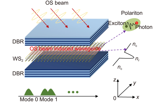
Mahnoor Shahzadi, Chuyuan Zheng, Sheraz Ahmad, Shanshan Wang, and Weili Zhang*
Author Affiliations
  • [in Chinese]
  • show less
    DOI: 10.29026/oea.2022.200066 Cite this Article
    Mahnoor Shahzadi, Chuyuan Zheng, Sheraz Ahmad, Shanshan Wang, Weili Zhang. Exciton-polariton based WS2 polarization modulator controlled by optical Stark beam[J]. Opto-Electronic Advances, 2022, 5(11): 200066 Copy Citation Text show less
    Structure of proposed model.The optical Stark beam is added to the cavity and a waveguide generated. The directions used in this paper are set by the coordinate.
    Fig. 1. Structure of proposed model.The optical Stark beam is added to the cavity and a waveguide generated. The directions used in this paper are set by the coordinate.
    Two level excitonic states and their strong coupling with cavity photons when the OS beam is added.
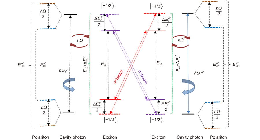
    Fig. 2. Two level excitonic states and their strong coupling with cavity photons when the OS beam is added.
    Effective refractive index versus OS shift “ΔExσ+”.
    Fig. 3. Effective refractive index versus OS shift “ ΔExσ+ ”.
    Mode profile of polariton wavepacket for polarized OS beam whenΔExσ+= 5 meV. (a) Only one mode is supported atΔExσ+= 5 meV. (b) A full map of the field distribution in the x-y plane atΔExσ+= 5 meV.
    Fig. 4. Mode profile of polariton wavepacket for polarized OS beam when ΔExσ+ = 5 meV. (a) Only one mode is supported at ΔExσ+ = 5 meV. (b) A full map of the field distribution in the x-y plane at ΔExσ+ = 5 meV.
    Mode profile and value of polarization degree ρ.(a) two modes are supported atΔExσ+=22meV andΔExσ−=0meV . (b) The full map of the field distribution in the x-yplane atΔExσ+=22meV andΔExσ−=0meV. (c) The modulation curves of ρ along the x-direction when y = 0 atΔExσ+=22meV andΔExσ−=5meV. (d) The full map of valueρin the x-y plane atΔExσ+=22meV andΔExσ−=5meV.
    Fig. 5. Mode profile and value of polarization degree ρ.(a) two modes are supported at ΔExσ+=22 meV and ΔExσ=0 meV . (b) The full map of the field distribution in the x-yplane at ΔExσ+=22 meV and ΔExσ=0 meV. (c) The modulation curves of ρ along the x-direction when y = 0 at ΔExσ+=22 meV and ΔExσ=5 meV. (d) The full map of value ρ in the x-y plane at ΔExσ+=22 meV and ΔExσ=5 meV.
    Typical modulation curves of ρ along the waveguide (x direction) for y = 0. The black curve corresponds toΔExσ+= 5 meV andΔExσ−= 0 meV, the blue curve corresponds toΔExσ+= 22 meV andΔExσ−= 5 meV, the red curve corresponds toΔExσ+= 5 meV andΔExσ−= 22 meV.
    Fig. 6. Typical modulation curves of ρ along the waveguide (x direction) for y = 0. The black curve corresponds to ΔExσ+ = 5 meV and ΔExσ = 0 meV, the blue curve corresponds to ΔExσ+ = 22 meV and ΔExσ = 5 meV, the red curve corresponds to ΔExσ+ = 5 meV and ΔExσ = 22 meV.
    Mahnoor Shahzadi, Chuyuan Zheng, Sheraz Ahmad, Shanshan Wang, Weili Zhang. Exciton-polariton based WS2 polarization modulator controlled by optical Stark beam[J]. Opto-Electronic Advances, 2022, 5(11): 200066
    Download Citation