
Rumao Tao, Xiaolin Wang, Hu Xiao, Pu Zhou, Lei Si. Coherent beam combination of fiber lasers with a strongly confined tapered self-imaging waveguide: theoretical modeling and simulation[J]. Photonics Research, 2013, 1(4): 186
- Photonics Research
- Vol. 1, Issue 4, 186 (2013)
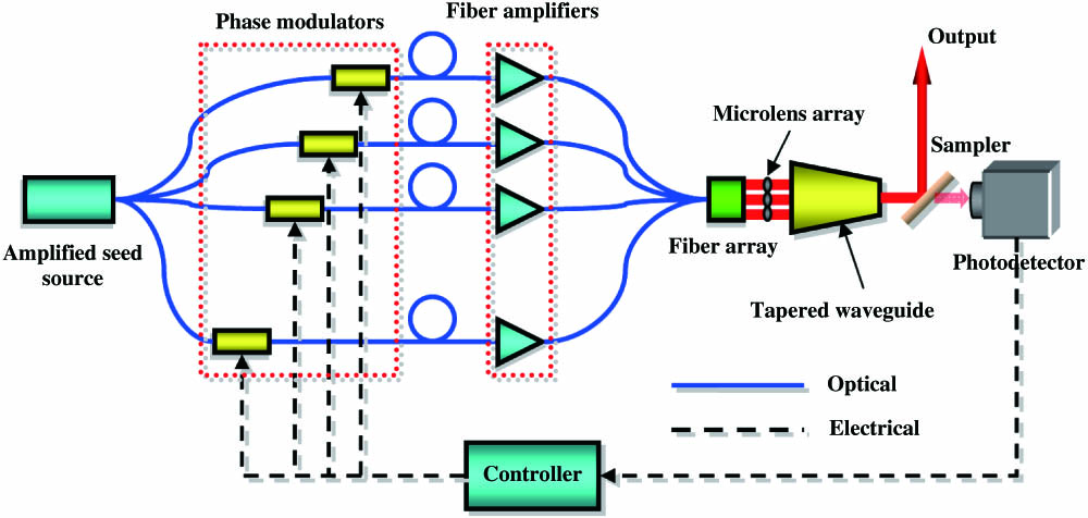
Fig. 1. Schematic diagram of the waveguide-based CBC system.
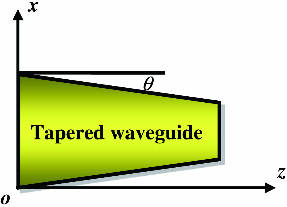
Fig. 2. Schematic diagram of a tapered waveguide.
Fig. 3. Amplitude distribution in the SCTW for Gaussian beam propagation. (a) Offset input Gaussian beam and (b) axially aligned input Gaussian beam.
Fig. 4. Field distribution at the output of the SCTW. (a), (c), (e), and (g) are for the self-imaging of the laser beam; (b), (d), (f), and (h) are for the combination application.
Fig. 5. Field distributions at the output of the SCTW for different taper angles. (a), (c) Amplitude distribution and (b), (d) Phase distribution.
Fig. 6. 3 × 3
Fig. 7. Transverse intensity distribution of 3 × 3
Fig. 8. Transverse intensity distribution of 3 × 3
Fig. 9. Optimal designation of the system and the results. (a) M 2 t t t
Fig. 10. M 2 t
Fig. 11. Dependence on taper angle. N = 2 W 1 = 50 μm
Fig. 12. Combining based on 2D SCWT. (a) Schematic diagram of a 2D tapered waveguide, (b) intensity distribution of input laser beams, and (c) intensity distribution of output laser beams.
|
Table 1. Parameters of the Tapered Waveguide
|
Table 2. Parameters for Setting of
|
Table 3. Parameters of the Square-Cross Tapered Waveguide
|
Table 4. Results of Two Kinds of CBC Systems

Set citation alerts for the article
Please enter your email address
© Copyright 2018-2021 | Chinese Laser Press. All Rights Reserved 沪ICP备15018463号-20