
Jianing Li, Chunshu Li, Zhaoyang Cheng, Wenyang Chen, Huan Luo, Yuyang Feng, Wenchao Jiang. Multi Mode Reconfigurable Terahertz Microstrip Antenna Based on Graphene[J]. Laser & Optoelectronics Progress, 2022, 59(3): 0316006
- Laser & Optoelectronics Progress
- Vol. 59, Issue 3, 0316006 (2022)
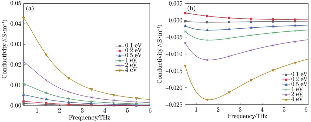
Fig. 1. Relationship between conductivity and frequency under different chemical potentials. (a) Relationship between the real part of conductivity and frequency; (b) relationship between the imaginary part of conductivity and frequency
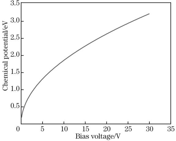
Fig. 2. Relationship between bias voltage and chemical potential of graphene
Fig. 3. Geometric structure of the antenna. (a) Top view; (b) bottom view
Fig. 4. Echo parameters in switch mode
Fig. 5. Radiation pattern of the antenna in switch mode. (a) E side; (b) H side
Fig. 6. Current distribution on the back of the antenna. (a) state 2; (b) state 5
Fig. 7. Echo parameters in fine-tuning mode
Fig. 8. Radiation pattern of the antenna in fine-tuning mode. (a) E side; (b) H side
Fig. 9. Current distribution on the back of the antenna. (a) state 5.1; (b) state 5.2; (c) state 5.3; (d) state 5.4; (e) state 5.5
|
Table 1. Size parameters of the antennaunit: μm
|
Table 2. Mode of antenna switch
|
Table 3. Performance parameters of antenna switch mode
|
Table 4. Fine-tuning modes of graphene
|
Table 5. Performance parameters of fine-tuning mode antenna

Set citation alerts for the article
Please enter your email address
© Copyright 2018-2021 | Chinese Laser Press. All Rights Reserved 沪ICP备15018463号-20