• Acta Optica Sinica
  • Vol. 40, Issue 20, 2011002 (2020)
Wenyu Cui1, Wenjuan Huang1、2, and Weining Yi1、*
Author Affiliations
  • 1Key Laboratory of Optical Calibration and Characterization, Anhui Institute of Optics and Fine Mechanics, Chinese Academy of Sciences, Hefei, Anhui 230031, China
  • 2University of Science and Technology of China, Hefei, Anhui 230026, China
  • show less
    DOI: 10.3788/AOS202040.2011002 Cite this Article Set citation alerts
    Wenyu Cui, Wenjuan Huang, Weining Yi. Calibration and Preprocessing Method for Amplitude Divided Simultaneous Imaging Polarimeter[J]. Acta Optica Sinica, 2020, 40(20): 2011002 Copy Citation Text show less
    Schematic of three-beam simultaneous polarization imaging system
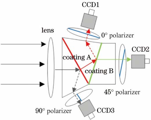
    Fig. 1. Schematic of three-beam simultaneous polarization imaging system
    Calculation results of polarization measurement errors caused by various error sources of beam splitting polarization imaging system. (a) Polarizer oriented angle error ak; (b) light divided ratio error bk; (c) transmissivity non-uniformity error ck; (d) radiation responsivity non-uniformity error di,j,k; (e) pixel offset ek
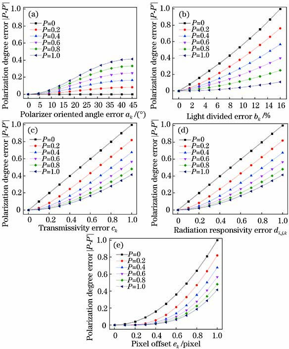
    Fig. 2. Calculation results of polarization measurement errors caused by various error sources of beam splitting polarization imaging system. (a) Polarizer oriented angle error ak; (b) light divided ratio error bk; (c) transmissivity non-uniformity error ck; (d) radiation responsivity non-uniformity error di,j,k; (e) pixel offset ek
    Calculation results of polarization angle measurement errors caused by various error sources of beam splitting polarization imaging system. (a) Polarizer oriented angle error ak; (b) light divided ratio error bk; (c) transmissivity non-uniformity error ck; (d) radiation responsivity non-uniformity error di,j,k; (e) pixel offset ek
    Fig. 3. Calculation results of polarization angle measurement errors caused by various error sources of beam splitting polarization imaging system. (a) Polarizer oriented angle error ak; (b) light divided ratio error bk; (c) transmissivity non-uniformity error ck; (d) radiation responsivity non-uniformity error di,j,k; (e) pixel offset ek
    Flow chart of pre-processing calibration for beam splitting simultaneous polarization imaging system
    Fig. 4. Flow chart of pre-processing calibration for beam splitting simultaneous polarization imaging system
    Calibration system of CCD non-uniformity. (a) Schematic diagram; (b) physical graph
    Fig. 5. Calibration system of CCD non-uniformity. (a) Schematic diagram; (b) physical graph
    Three-channel original image pixel value. (a) Image of 0° polarizer; (b) image of 45° polarizer; (c) image of 90° polarizer
    Fig. 6. Three-channel original image pixel value. (a) Image of 0° polarizer; (b) image of 45° polarizer; (c) image of 90° polarizer
    Three-channel image pixel value after uniformity correction. (a) Image of 0° polarizer; (b) image of 45° polarizer; (c) image of 90° polarizer
    Fig. 7. Three-channel image pixel value after uniformity correction. (a) Image of 0° polarizer; (b) image of 45° polarizer; (c) image of 90° polarizer
    Three-channel radiation response difference calibration system. (a) Schematic diagram; (b) physical graph
    Fig. 8. Three-channel radiation response difference calibration system. (a) Schematic diagram; (b) physical graph
    Calibration system for polarizer oriented angle. (a) Schematic diagram; (b) physical graph
    Fig. 9. Calibration system for polarizer oriented angle. (a) Schematic diagram; (b) physical graph
    Fitting curves of pixel values of different polarized angles. (a) 0° polarization channel; (b) 45° polarization channel; (c) 90° polarization channel
    Fig. 10. Fitting curves of pixel values of different polarized angles. (a) 0° polarization channel; (b) 45° polarization channel; (c) 90° polarization channel
    Comparison of polarization degree measurement error before and after correction for amplitude divided imaging polarimeter. (a) Before correction; (b) after correction
    Fig. 11. Comparison of polarization degree measurement error before and after correction for amplitude divided imaging polarimeter. (a) Before correction; (b) after correction
    Comparison of polarization angle measurement error before and after correction for amplitude divided imaging polarimeter. (a) Before correction; (b) after correction
    Fig. 12. Comparison of polarization angle measurement error before and after correction for amplitude divided imaging polarimeter. (a) Before correction; (b) after correction
    Stokes parameter images after preprocessing. (a) Image of I parameter; (b) image of Q parameter; (c) image of U parameter; (d) image of polarization degree; (e) image of polarized angle
    Fig. 13. Stokes parameter images after preprocessing. (a) Image of I parameter; (b) image of Q parameter; (c) image of U parameter; (d) image of polarization degree; (e) image of polarized angle
    Comparison between original image and polarization fusion image. (a) Original image; (b) polarization fusion image
    Fig. 14. Comparison between original image and polarization fusion image. (a) Original image; (b) polarization fusion image
    ParameterValue
    Detection band /nm500-1000
    Pixel number1392 ×1040
    Pixel size /(μm×μm)6.45×6.45
    CCD size /(cm×cm)24×36
    Digitalizing bit8 or 12
    Max FPS /(frame/s)30
    Focal length /mm51.7
    Polarization angles /(°)0,45,90
    Camera FOV /(°)10×7.6
    Table 1. Polarization imaging system parameters
    Lightσ1σ2σ3
    12.742.843.33
    22.572.762.94
    32.552.692.79
    42.422.712.72
    52.372.622.66
    62.382.622.62
    72.332.592.60
    82.392.602.58
    Average2.472.682.78
    Table 2. Non-uniformity σ of three-channel original imageunit: %
    Lightσ1σ2σ3
    10.820.800.95
    20.460.440.53
    30.400.360.44
    40.330.320.38
    50.290.270.33
    60.300.280.34
    70.260.240.31
    80.220.190.26
    Average0.390.360.44
    Table 3. Non-uniformity σ of three-channel image after uniformity correctionunit: %
    Light2468
    DN¯(0°)556.441138.651685.002249.34
    DN¯(45°)555.431136.241686.512249.34
    DN¯(90°)555.851133.841686.632252.58
    Table 4. Three-channel image average after radiation response uniformity correction
    Light2468Average
    ε2Original15.3416.4517.1417.2316.54
    Corrected-0.18-0.210.090.00-0.08
    ε3Original-19.59-18.27-17.32-17.04-18.06
    Corrected-0.11-0.420.100.14-0.07
    Table 5. Relative difference ratio of average DN of 3 channel images before and after radiation responsivity uniformity correctionunit: %
    Nominal value /(°)Measuring value /(°)Polarizer oriented angle error /(°)
    00.000.00
    4543.26-1.74
    9088.32-1.68
    Table 6. Measuring results of polarizer oriented angles
    Errorθk /(°)ak/(°)εkσkek
    Before correction00.000.00000.02470.00
    45-1.740.16540.02682.01
    90-1.68-0.18060.02782.12
    After correction00.000.00000.00390.00
    45-1.74-0.00080.00360.22
    90-1.68-0.00070.00440.18
    Table 7. Calibration values of system errors
    Wenyu Cui, Wenjuan Huang, Weining Yi. Calibration and Preprocessing Method for Amplitude Divided Simultaneous Imaging Polarimeter[J]. Acta Optica Sinica, 2020, 40(20): 2011002
    Download Citation