A. Calabrese, F. Ramiro-Manzano, H. M. Price, S. Biasi, M. Bernard, M. Ghulinyan, I. Carusotto, L. Pavesi, "Unidirectional reflection from an integrated “taiji” microresonator," Photonics Res. 8, 1333 (2020)
Copy Citation Text
We study light transmission and reflection from an integrated microresonator device, formed by a circular microresonator coupled to a bus waveguide, with an embedded S-shaped additional crossover waveguide element that selectively couples counter-propagating modes in a propagation-direction-dependent way. The overall shape of the device resembles a “taiji” symbol, hence its name. While Lorentz reciprocity is preserved in transmission, the peculiar geometry allows us to exploit the non-Hermitian nature of the system to obtain high-contrast unidirectional reflection with negligible reflection for light incident in one direction and a significant reflection in the opposite direction.
1. INTRODUCTION
Over the years, strong efforts within the optical community have been focused on the implementation of unidirectional optical circuits showing different behaviors depending on the direction in which light is incident onto them. Since it is not possible to violate the reciprocity theorem of Lorentz in linear systems without using non-reciprocal, e.g., magnetic elements, the realization of a miniaturized optical isolator capable of working in the linear regime is still a challenging task [1].
Restricting ourselves to those non-magnetic materials that can be easily integrated on a standard silicon photonics platform, interesting direction-dependent features can be obtained by suitably engineering a non-Hermitian dynamics. In particular, while Lorentz reciprocity imposes equal transmission in the two propagation directions, the reflection coefficients can have completely different behaviors [2].
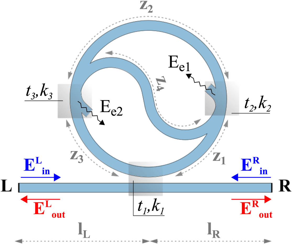
In this perspective, a promising device is the so-called “taiji” resonator sketched in Fig. 1, namely a ring cavity embedding an S-shaped crossover branch that selectively couples the counter-propagating cavity modes. Other names under which similar devices are known in the literature include “spectacles-shaped ring resonator” [3], “theta cavities” [4], and “yin-yang cavities” [5]. A bus waveguide laterally coupled to the resonator is used to inject light into it. Such devices were first introduced in the design of a cavity for achieving unidirectional lasing in a circular Y-junction ring diode laser [6]. After that, they have also been used to build unidirectional fiber lasers [5], to introduce electromagnetically induced transparency (EIT) [7] and to control light velocity in monolithic microfibers [8]. Very recently, arrays of such cavities were used for topological laser operation [9]. Even though light transmission in the linear regime remains reciprocal, the intrinsic nonlinearity of laser operation combined with the breaking of the left-right symmetry by the S-shaped branch was responsible for an efficient unidirectional laser operation.
Sign up for Photonics Research TOC. Get the latest issue of Photonics Research delivered right to you!Sign up now
Figure 1.Sketch of the taiji microresonator: and ( and ) are input (output) field amplitudes at the left and right facet, respectively, while and are the amplitudes of fields emitted as radiative dissipation; and , with , are the coupling and transmission amplitudes at the different beamsplitting regions indicated by the gray squares. The gray dashed lines define the spatial size of the different segments.
Despite their successful use in unidirectional lasers and in topological systems, a detailed study of the transmission and reflection properties in a waveguide/microresonator system is lacking. To establish the basis of further developments, here we present a detailed study of a taiji device fabricated on an integrated silicon photonics platform and probed through a bus waveguide. Its transmission and reflection properties at linear optical level are investigated both analytically and numerically as well as experimentally. The expected reciprocity of the transmission is accurately confirmed by the experiment and a good contrast in the direction-dependent reflection is found. In particular, we show that the reflection asymmetry is robust against the Fabry-Perot fringes due to spurious reflections at the ends of such a bus waveguide. Our results confirm the promise of taiji resonator elements to obtain unidirectional reflection in an optical integrated circuit.
2. THEORY AND SIMULATION
A. Analytical Model
Let us consider a bus waveguide coupled to a taiji microresonator, as sketched in Fig. 1. We assume that all light-guiding components in the system are single-mode and made of a linear and homogeneous material. We define and ( and ) as the field amplitudes of the input (output) left and right facet. Since the excited field is butt-coupled to the sample, the theoretical model must take into account the Fabry–Perot cavity created by the bus waveguide. We assume that, other than reflections at the input and output facets, there is no source of back-reflection in the system, neither from back-scattering in the ring nor from reflections at the ends of the embedded S-shaped branch. Back-scattering is often present in microresonator systems and can introduce non-Hermitian dynamics [10]. However, its effects are evident in resonators with high/ultra-high quality factors, where the surface wall roughness becomes the dominant source of the intrinsic losses. This is not our case. Therefore, in the following, we will only focus on the non-Hermitian dynamics induced by the presence of the embedded branch.
To model the whole system, we use the transfer matrix approach [11]. In this way, the input and output fields at the left facet are related to those at the right facet as where is the matrix product of different contributions: . In particular, and are associated with the right and left facet of the system which are given by where and are the transmission and reflection from the facet. The different sign in reflection between the two matrices reflects the fact that the interfaces are crossed in opposite directions. and are associated with the propagation along the length between the taiji and the right and left facet, respectively. These take the following form: where we have introduced the notation to denote the phase shift and attenuation accumulated over the length , where .
is the transfer matrix of the taiji microresonator. This is schematized as the combination of three lossless and reciprocal beamsplitters or directional couplers, as shown in Fig. 1 (see Appendix A). Such beamsplitters are characterized by their coupling and transmission amplitudes, respectively given by and , with and real-valued and . Reciprocity and losslessness imply that . Segments of the ring separating the beamsplitters are characterized by their length , with ; guided modes propagate freely in these regions. The transfer matrix of the taiji is the following: where is the perimeter of the external ring circumference, and . is the propagation constant of the guided mode while is the loss coefficient of the taiji.
To better understand the transmission and reflection properties of the system, it is useful to look at its scattering matrix , which relates the left and right output fields to the input ones, Its matrix elements have a direct physical meaning, representing reflection and transmission amplitudes.
If we restrict ourselves to the simpler system consisting of a taiji microresonator coupled to a bus waveguide with no reflection at its end facets, the scattering matrix has the form where () is the reflection amplitude for light incident from the left (right) end of the bus waveguide, while and represent transmission from left to right and vice versa (the derivation of the matrix and the relation with are reported in Appendix A).
In agreement with the Lorentz reciprocity theorem, the scattering matrix is symmetric, i.e., transmission to both sides is the same. The on-diagonal elements instead are different, giving a direction-dependent reflection. This stems from the non-unitarity of the scattering matrix and the left/right asymmetric geometry of the device. While light propagating in the clockwise direction penetrates into the S-shaped branch with no losses and is then transferred to the counter-propagating mode, light that is initially propagating in the counter-clockwise mode is radiated into unguided modes of the cladding at the end points of the S-shaped branch, as schematized by the black wavy arrows in Fig. 1. Since our interest is limited to the behavior of the taiji for incident and transmitted/reflected light through the waveguide, these radiated waves do not contribute to our reflection/transmission properties which are encapsulated in a transfer matrix, with loss terms that implicitly incorporate the effect of the radiated waves.
From the analytical form [Eq. (6)] of the taiji scattering matrix , it is immediate to see how the effect of the S-branch on the transmission is just an extra contribution to the intrinsic losses per round-trip proportional to , which shifts the critical coupling condition. Depending on the counter-clockwise or clockwise propagation direction, these losses correspond to direct losses into unguided modes or irreversible transfer to the oppositely propagating mode.
Because of the double resonance condition involved (see the square in the denominator of the expression for ) the resonance peak in the reflectivity for light incident from the right has a narrower shape. A remarkable condition of perfect unidirectional reflection with and is found in the critical coupling regime. This regime is easily met in the absence of propagation losses for suitably balanced beamsplitters such that , which corresponds (for small ) to equal losses in the bus waveguide and in the S-branch . On the contrary, the reflection coefficient for an excitation on the other side is reduced to zero (), and therefore, all light is dissipated at the end points of the S-branch.
These remarkable unidirectional reflection properties of the taiji directly reflect into analogous properties for the whole device including the bus waveguide and reflections at its ends. From Eq. (1), one can derive the transmission amplitude of the whole system in either direction (i.e., light incident from left or from right) as : where and . As expected from the Lorentz reciprocity theorem the transmission in both directions is the same. On the other hand, the reflection amplitude from light incident from the left (right) is defined as (), and As we shall see in the following, reflections at the end of the waveguide give rise to additional features in the spectra that complicate the analysis, but still the asymmetric intrinsic reflection of the taiji remains well visible in the experiment in good quantitative agreement with the theory.
B. Numerical Simulation
Before moving to experiments, we have verified the predictions of the analytic model through a finite element method (FEM) simulation engine by COMSOL Multiphysics controlled by the mathematical programming environment of MATLAB. This was of great utility also as a guide towards the proper design for fabrication.
The main results are reported in Figs. 2(a) and 2(b). The taiji is drawn in a two-dimensional geometry. It is made of silicon oxynitride () embedded in air. The refractive indices are, respectively, 1.83 and 1 at the frequency , corresponding to the free-space wavelength μ. The S-branch ends are evanescently coupled to the ring and the coupling is point-like. The separations between ring and branch ends are set so as to have . The one between ring and bus waveguide is set so to have (see Appendix B). The coupling between the bus waveguide and the ring resonator is fixed in the critical-coupling regime. Since we are assuming that there is no power dissipation in the system (), the intrinsic losses are given by the coupling to the S-shaped branch. The electric field distribution in the taiji is computed in response to a monochromatic incident field of variable frequency.
Figure 2(a) shows the device response to an input fed from the left, whose frequency is resonant with the cavity formed by the ring. It can be seen clearly that the injected power flows to the ends of the embedded branch, from which it will be transmitted to the cladding and then dissipated. Indeed, in the simulation the ends of the S-shaped branch are treated as open boundary ports and do not generate any reflection. Thanks to the assumed critical coupling condition, the transmission to the right end of the bus waveguide is null as well as the reflection to the left. Figure 2(b) shows the response to a signal of same frequency, but injected from the right. As predicted in the analytical model, both the counter-propagating modes of the ring are now excited and reflection to the right is total. More precisely, the incident light enters into the ring and travels clockwise along it. Upon coupling into the S branch, it reverses its direction and ends up propagating in the counter-clockwise direction in the ring. Once this light leaks out from the ring cavity into the bus waveguide, it propagates back to the right and gives rise to the reflected wave.
Figure 2.Panels (a) and (b): numerical results for the field intensity in the taiji microresonator with light incident from the left and right, respectively. The geometrical dimensions are in μm. The frequency is resonant with the ring and the bus waveguide is critically coupled. The color plot shows the electric field amplitude in V/m. It is noteworthy that only light incident from the right excites the S waveguide. This highlights the non-symmetrical behavior of light reflection. Panels (c) and (d): transmitted (blue dots) and reflected intensity as a function of the incident wavelength for light incident from the left (black dots) and from the right (green dots). The red lines display the fitting results employing the analytical model.
By comparing Figs. 2(a) and 2(b), it is interesting to note that radiation from the ends of the S-shaped branch into the cladding is present when the incident radiation comes from the left, but not when it comes from the right. This is due to a subtle destructive interference effect between the light that propagates along the S-branch and the light that is injected into the S-branch next to its end. In the language of Fig. 7 in Appendix A, this interference occurs between fields and into and between and into , and it is captured by the analytical formulas [Eqs. (A7) and (A8)]. Interestingly, this interference is perfectly destructive only on resonance, while the amount of radiated power into the cladding can attain significant levels for non-resonant incident light.
Figures 2(c) and 2(d) show the transmission (blue dots) and the reflection (black and green dots) spectra as a function of the incident wavelength, for a signal injected from the left and the right, respectively. The red lines display the fitting results employing the analytical Eqs. (7)–(9). Given the specific configuration considered in the numerics, reflections at the ends of the bus waveguide are absent ( and ). Fixing the FEM geometrical and material parameters, the analytical model reproduces accurately the simulation results. The three data sets employed were simultaneously fitted reducing the mutual dependence of the free, or in this case better to say, shared parameters among equations. The goodness of the fitting results provides a first validation of the analytical model in an extreme regime where the asymmetric reflection is perfect.
3. EXPERIMENTAL RESULTS
A. Samples and Experimental Setup
The samples studied were taiji microresonators coupled to a bus waveguide. The top-view of the sample is shown in the optical micrograph of Fig. 3(a). Precisely, the system is composed by single mode channel waveguides of silicon oxynitride (SiON) on top of a 5 μm thermal silica () grown on 6-inch (0.1524 m) silicon (Si) wafers. The waveguides width is 1.2 μm while the height is 0.57 μm. The light is confined between the lower thermal oxide cladding and the upper one, constituted by a double stack of 410 nm borophosphosilicate glass (BPSG) and a 2 μm thick PECVD SiOx layer. The scanning electron microscopy (SEM) image of the cross-section is shown in Fig. 3(b). More details about the fabrication of the samples are reported in Ref. [12]. As shown in Fig. 3(a), the taiji device consists of a racetrack resonator coupled to a bus waveguide. The curve segments are composed by 90 deg arcs of 25 μm in radius for achieving negligible bending losses. The three coupling regions consist of directional couplers, with a length and a gap of μ and μ for the two S-shape branches, and μ and μ for the bus waveguides. In addition, as can be seen from the optical micrograph of Fig. 3(a), the ends of the S waveguide are progressively widened. This peculiar geometry is known as mode killer [13,14], and allows for the suppressing of the mode propagation. Specifically, it permits us to avoid reflections at the ends of the S-shape branch.
Figure 3.Panels (a) and (b) show the optical micrograph and the SEM image of the top and the cross-section view of a taiji microresonator, respectively. Panel (c): sketch of the experimental setup.
Figure 3(c) shows the sketch of the experimental setup. A fiber-coupled continuous wave tunable laser (red) is used as the source. It operates at 3 mW in the range spanning from 1470 nm to 1580 nm. The source is protected by an optical isolator (yellow), which avoids any back-reflection. Its emission is adjusted in polarization by a polarization control stage. After this stage, an optical circulator (green) routes the light coming from the source into a lensed tapered fiber, which couples the light into the sample. At the other end of the sample, another lensed tapered fiber collects the transmitted light, which is then measured by a germanium (Ge) detector. The light reflected by the sample back into the input fiber is routed by the optical circulator to a twin detector, which collects the reflected light. As the reflected signal is much weaker than the transmitted, the reflection detector has a 20 dB amplification with respect to the transmission one. When the tunable laser sweeps in frequency, the signal of both detectors is acquired simultaneously with an oscilloscope. Therefore, the transmission and reflection spectra are acquired at the same time. The two configurations with light incident either from the left or from the right are selected by varying the orientation of the sample within the optical setup.
B. Experimental Measurements
As a first step, the propagation loss of the waveguide structures was assessed using the Beer-Lambert law. Dedicated structures, with folded waveguides of different length, have been realized on the chip to this aim. As reported in Ref. [12], the propagation losses have been measured to be for both transverse electric (TE) and transverse magnetic (TM) polarizations at 1567 nm. The coupling losses have been estimated with the cut-back technique, which gives , equally divided between input and output.
The transmission and reflection of the full system including the bus waveguide and the taiji structure were then measured. Figure 4 shows the transmitted [Fig. 4(a)] and reflected intensity when the input is fed on the right [Fig. 4(b)] and on the left [Fig. 4(c)]. The blue points are the experimental data. The input light is set in the TE polarization. The transmission spectrum shown in Fig. 4(a) displays a series of strong resonant dips within fast Fabry–Perot oscillations due to the reflections at the end of the waveguide. As expected from the Lorentz reciprocity theorem, the transmission is equal in the two configurations, which confirms the accuracy of our measurement.
Figure 4.Experimental spectra of the (a) transmitted and (b), (c) reflected intensities as a function of the incident wavelength. The blue lines show the experimental measurements while the red lines display the fitting results employing the analytical model. The bottom panels show the zoom of the transmitted (Zoom 1) and reflected (Zoom 2, 3) intensities for the resonance highlighted by the vertical dashed lines.
On the other hand, the two reflection amplitudes are different. In particular, the reflection amplitude for light incident from right exhibits resonance peaks [see Fig. 4(b)], while the reflection amplitude for light incident from left only features the usual Fabry–Perot fringes [see Fig. 4(c)]. Therefore, the device works as a unidirectional reflector. The different heights of the reflection peaks of Fig. 4(b) can be physically understood in terms of the beating of the Fabry–Perot fringes with the resonant peaks, namely the interference between the field that is reflected at the end of the waveguide and the one that is reflected within the taiji.
A more quantitative insight on these features can be obtained from our analytical model. The red lines show the fitting results employing the theoretical model of Section 2 [Eq. (7) for the transmission amplitude and Eqs. (8) and (9) for the reflection amplitude]. From the figure, it appears that these models are able to accurately reproduce the experimental observations. Note that also in this case, the three data sets, i.e., intensity transmitted and reflected in the two directions of excitation, have been simultaneously fitted by fixing the geometric sizes and the effective index of the material. The final size of the fabricated device and waveguide profile were readjusted from the nominal design by means of the SEM images, while the effective index was determined thanks to the ellipsometry data and FEM simulations. It is worth noticing that the fit of the experimental data allows us to estimate the amplitude of reflection of the facets equal to . This value is in good agreement with the index contrast between the air and core medium. In addition, from the transmitted intensity spectrum it is easy to estimate a quality factor of about for the resonance shown in the bottom panel of Fig. 4. More details on the free and fixed parameters used in the fitting process are reported in Appendix B.
In order to quantify the difference between the two reflection intensities, Fig. 5 shows the values of the fitted functions at the resonant wavelengths (). Precisely, the red squares show the transmitted intensity (), the upward light blue triangles denote the reflected intensity for light incident from right (), and the downward blue triangles depict the reflected intensity for light incident from left (). The and coefficients contain contributions from the taiji microresonator as well as from the reflection at the bus waveguide facets (Fabry–Perot effect). Consequently, the reflected intensity for light incident from left does not reduce to zero as in the case of vanishing reflections at the end facets of the bus waveguide. However, comparing the upward with the downward triangles, one can see that the is significantly lower than for all the resonant wavelengths across the spectrum. Specifically, the average values of the resonant and intensities correspond to 0.376 and 0.184, respectively. Therefore, the average value of the is about twice the average value of (see the difference between the light blue and the blue dashed lines in Fig. 5). This shows that the reflection asymmetry derived for the taiji microresonator is robust against the reflections at the ends of the bus waveguide.
Figure 5.Intensity as a function of the wavelength computed with the Eqs. (7) and (8) using the parameters of Table 1 (Appendix B) at the resonant wavelengths (). Precisely, the red squares are the transmitted intensity, the upward light blue triangles are the reflected intensity for light incident from right and the downward blue triangles are the reflected intensity for light incident from left. The light blue and blue dashed lines denote the average of the resonant values for the and the , respectively.
Of course, it is possible to decrease the oscillations of the Fabry–Perot by introducing a different type of fiber-to-chip coupling, such as matched index resin, grating couplers or inverse coupling [15] which could limit the spurious reflection at the waveguide ends, and . In this way, the intrinsic properties of the taiji could be isolated and the transmission and reflection could simplify and match the ideal ones illustrated in Fig. 2.
4. CONCLUSION
In this work, we have reported a joint theoretical and experimental study of the linear optical transmission and reflection properties of a taiji microresonator excited via a bus waveguide. Such a structure consists of a microring resonator, with an embedded additional S-shaped element, which provides a selective direction-dependent coupling of counter-propagating modes. An analytical model based on transfer matrices has been presented and validated against numerical simulations based on an FEM software. The device has been realized on a integrated silicon photonics platform and spectroscopic measurements have confirmed theoretical predictions. In particular, we have demonstrated that the taiji resonator indeed works as a unidirectional reflector in spite of the presence of spurious reflections at the ends of the bus waveguide. In fact, even though the transmission is the same for light incident from the left or from the right, the reflection peaks only appear for one direction of incidence. The analytical insight on the linear optical features provides a fundamental step towards the full exploitation of a family of devices that holds great promise in view of obtaining new behaviors when endowed with optical gain and/or optical nonlinearities.
Acknowledgment
Acknowledgment. I.C. acknowledges funding from Provincia Autonoma di Trento, Italy and from the European Union via the H2020-FETFLAG-2018-2020 Quantum Flagship and the FET-Open. F.R.M acknowledges the support of the Spanish Ministry of Economy, Industry and Competitiveness (MINECO) through the project “MiNa”. H.M.P acknowledges funding from the Provincia Autonoma di Trento, through the project “On silicon chip quantum optics for quantum computing and secure communications–SiQuro”; from the European Commission; and from the Royal Society.
APPENDIX A: DERIVATION OF TAIJI TRANSFER AND SCATTERING MATRICES
We report here the analytic calculations through which we derived the scattering matrix of the taiji resonator [Eq.?(6)], from which we eventually calculated the transfer matrix [Eq.?(4)]. As stated in the main text, we assume that bus waveguide, ring, and S-shaped branch are all single-mode. Any signal sent to the taiji is thus identified only by its guided-mode amplitude. As illustrated in Figs.?6 and 7 by the gray squares, the taiji is the combination of three beamsplitters: the first one corresponds to the region of evanescent coupling between the bus waveguide and the bottom of the ring, while the second and third are the regions of evanescent coupling between the ring and the S-shaped branch. For simplicity, we will ignore here the presence of the bus waveguide facets and we will assume , so that we focus only on the interactions taking place in the taiji.
Figure 6.Map of the fields within the device, used to calculate the scattering matrix elements when light enters from the left. Labels , with , represent complex amplitudes of the guided fields propagating in the device. Labels and indicate the modes that are radiated into the cladding. and , where , are the transmission and coupling amplitudes at the different beamsplitting regions.
Figure 7.Map of the fields within the device, used to calculate the scattering matrix elements when light enters from the right. Again , with integers, are complex amplitudes of guided-mode fields, while and indicate the amplitudes of the modes that are radiated into the cladding. and , where , are the transmission and coupling amplitudes at the different beamsplitting regions.
Let us first consider an input signal, with amplitude , that enters the system from the left. The process is schematized in Fig.?6: fields excited at the beamsplitters are identified by their amplitudes , with an integer ranging from one to six. Also included in the picture are the signals lost as radiation modes at the S-shaped branch ends, whose amplitudes are labeled and respectively. Such signal amplitudes are related by the following system of equations: We have denoted with and the (real) coupling and transmission amplitudes of the i-th beamsplitter respectively (), with . Propagation along the segments separating the beamsplitters leads to a phase shift proportional to the optical path, which in turn depends on the propagation constant , and an attenuation in amplitude proportional to , the attenuation coefficient per unit length, with ; is the distance traveled, with , where is the perimeter of the ring circumference.
For a given incident field , there is a unique solution to this system. The transmitted beam to the right is given by
For completeness, we report the expression of the in-cavity field, i.e., of the field propagating in the ring as from which we deduce that
We also computed expressions of the field amplitudes at the end points of the S-shaped branch, right before they are radiated to the embedding material. Such field amplitudes are labeled and in Fig.?1. This calculation is useful in order to get the radiated power spectrum and check conservation of energy in the system as follows:
It is worth noticing that the presence of the S branch inside the cavity reduces the amplitude of the electric field to zero (), and consequently the reflected beam is zero, i.e., .
Let us now consider the case of an input signal sent from the right. Again we consider the interactions taking place in the system, that are schematized in Fig.?7. Using the same notation as for the case of input from the left, the system of equations now reads as follows:
For a given incident field , the system has a unique solution. The amplitudes of the transmitted and the reflected beam amplitude are given by Again, we report the in-cavity fields for completeness. The field propagating clockwise has the same expression as in the previous case. The field originating from the reflection into the branch and propagating in the opposite direction is instead given by so that the reflected signal is written as Finally, the fields radiated from the S-shaped branch have the following amplitudes: which can be used to verify energy conservation.
Considering Eqs.?(1) and (5), the transformation from scattering () to transfer matrix () is finally performed using the following relation:
APPENDIX B: PARAMETERS FOR THE FINITE ELEMENT METHOD SIMULATIONS AND FITTING PROCESSES
In order to verify the validity of our analytical model for the taiji resonator, we performed finite element method simulations of the device optical response. The aim was to get a general, qualitative picture of the taiji interaction with light, that could confirm our analytical predictions and guide us toward the proper design for a fabrication.
The two-dimensional system geometry drawn for simulations, which can be seen in Fig.?2, is chosen to be the simplest possible for our purposes. The external radius of the ring resonator is set to 12?μm and the thickness of the waveguides to 500?nm. Since the waveguides are supposed to be made of , which has a refractive index of 1.83 at 1.55?μm, the waveguides have to be thinner than the wavelength of light in the material (847?nm), in order to ensure single-mode operation. The most crucial issue is to set the values of the beamsplitter parameters and (and consequently of and as well) from the geometry. As is usually done in many practical applications of microresonators, it is convenient to have lateral evanescent coupling between ring and bus waveguide. This means that the beamsplitting region, within which light is exchanged between the two, is small compared to the actual coupling length. In this way, the transmission amplitude is a monotonic function of the separation between bus waveguide and bottom of the ring, and the complex oscillatory coupling observed in vertical coupling geometries [16] is avoided. The same strategy can be applied to determine .
We performed separate simulations of the taiji beamsplitters, in order to derive the values of and independently. In a first simulation, we consider the bus waveguide and a segment of the ring, as can be seen in the inset of Fig.?8. Light is injected from the left end of the bus waveguide and transmission to ring and bus waveguide itself is evaluated, for different values of the mutual separation. Normalized transmitted intensities are plotted in Fig.?8. Similarly, we simulate the interaction region between ring and S-shaped branch (inset of Fig.?9). Light is injected from the ring and transmission to both output ports is evaluated as a function of separation (Fig.?9).
Figure 8.Results of the simulation of the ring-bus waveguide coupling region of the taiji. Plotted curves represent the power transmission to either the bus waveguide or the ring, as a function of their mutual separation. The inset shows the distribution of electric field amplitude in the system in V/m, for a chosen distance of 335 nm. Geometrical dimensions are in μm.
Figure 9.Results of the simulation of the ring-S-shaped waveguide coupling region of the taiji. Plotted curves represent the power transmission to either the ring or the S-shaped branch, as a function of their mutual separation. The inset shows the distribution of electric field amplitude in the system in V/m, for a chosen distance of 289 nm. Geometrical dimensions are in μm.
In order to obtain the optimal configuration where unidirectional reflection is most apparent, it is convenient to place ourselves in the critical coupling regime that is mentioned in the main text. From the plots of Fig.?8, we see that we have , and thus , for a ring–bus waveguide separation of 335?nm. In the same way, the plots of Fig.?9 allow us to set the ring–S-shaped branch separation to 289?nm, in order to get and thus .
The parameters fixed in the fitting procedure are the geometric dimensions of the taiji microresonator/waveguide. They were determined by the mask design and verified through SEM images. The fundamental free parameters used in the fitting process are: the reflection coefficients of the input and output facets, the linear losses of the material, the coupling coefficients related to the microresonator/bus waveguide, the S-shape embedded into the cavity, a wavelength shift between the and , and a deviation of the effective refractive index of the waveguide. The last one is just a constant added to the (experimental and numerical) procedure of obtaining the effective refractive index. In particular, we have extrapolated this effective dispersion by simulating (employing COMSOL Multiphysics) the cross-section of the waveguide using the bulk refractive index estimated by an ellipsometry technique. On the other hand, the wavelength shift parameter is necessary because exhibits an artificial and slight shift in wavelength with respect to the . This shift is strictly connected to tolerance of the wavelength repeatability of the laser source composed by an external tunable cavity. Obviously the consequences of this instrumental deviation has no physical meaning and is not included in the model, but has been considered in the fitting process, because and are measured at different times. In addition, we have introduced a normalization process similar to a typical baseline correction, but parametrized in this case by the different offset and gain of the two Ge detectors used to measure the transmission and reflection response. The free fitting and the fixed parameters are reported in Table?1.
[4] S. Kharitonov, C. Brés. Dual-emission band all-fiber laser based on theta cavity with thulium- and holmium-doped fibers. Optical Fiber Communications Conference and Exhibition (OFC), 1-3(2017).
A. Calabrese, F. Ramiro-Manzano, H. M. Price, S. Biasi, M. Bernard, M. Ghulinyan, I. Carusotto, L. Pavesi, "Unidirectional reflection from an integrated “taiji” microresonator," Photonics Res. 8, 1333 (2020)