
Xu Wang. Removal function research on the fused silica mirror with 400 mm polishing wheel of the magnetorheological finishing[J]. Chinese Optics Letters, 2015, 13(Suppl.): S22203
- Chinese Optics Letters
- Vol. 13, Issue Suppl., S22203 (2015)
Abstract
Using aspherical optical components in advanced optical systems not only reduces the system complexity, but also improves the performance remarkably. Compared with traditional spherical optical components, large aspherical surfaces are difficult to fabricate, which limits broad application in advanced systems.
Because of their complexity, so far there is no general high-accuracy aspherical manufacturing equipment. This kind of equipment is illegal to sell to China in the context of some important technologies, so it should be researched and developed in China.
Traditional optical fabrication technology is contact fabrication with pressure, which is readily influenced by the manufacturing environment and difficult to control, such as the polishing fluid (slurry) concentration, the temperature and chemical characteristics (and so on), the physical characteristics of the polishing pad and the workpiece, the pressure of the polishing load, and the relative velocity. In traditional polishing technology, subsurface damage will occur on the mirror surface, attributable to the polishing pressure. Because of this pressure, the polishing pad will be worn during the process, which means that the pad contact surface changes frequently. Consequently, the removal function of the technology is unstable. If one uses this kind of polishing pad, the workpiece surface error has very low repeatability and predictability. In contrast, noncontact polishing technology will have a very stable removal function in the process because of the absence of the working pressure. However, its biggest disadvantage is the low removal rate, which can only be used in the final finishing procedure.
Sign up for Chinese Optics Letters TOC. Get the latest issue of Chinese Optics Letters delivered right to you!Sign up now
Magnetorheological finishing (MRF) technology, developed in the 1990s, is a very useful contact polishing technology that works with normal levels of pressure, and uses tangential velocity to remove the mirror material. Not only does it have a high removal rate similarly to contact technology, but it also has a stable removal function similarly to noncontact fabrication technology[
Based on the aforementioned characteristics, if MRF technology is assembled on a large computerized numerical control (CNC) to fabricate a large mirror, the mid and low spacial frequency will be removed quickly[
A MRF polishing platform with a 400 mm diameter wheel is applied towards fast fabrication of a large aspherial mirror whose diameter is over 1 m-class. The 1 m-class mirror is usually fabricated by stressed lap polishing (SLP) or computer-controlled optical surfacing (CCOS). Its biggest disadvantage is the low fabrication efficiency in the fine polishing procedure, which causes the manufacturing period to be too long. Because of the high removal rate and stable removal function, MRF technology with a large polishing wheel is assembled on a large CNC, which combines both advantages and is suitable to fabricate large aspherical mirrors. The advantage of this assembly is embodied as the high fabrication efficiency of the large mirror and reducing the fabrication duration. The parameters of the large aspherical MRF CNC are described in Table
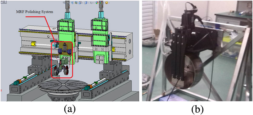
To examine the applicability of MRF-2500, anther 200 mm diameter MRF polishing wheel is assembled to the Z1 manufacturing axes, where a 400 mm MRF polishing wheel is mounted. This is called a “dual MRF wheel manufacturing center;” it is displayed in Fig.
![]()
Figure 1.MRF polishing system: (a) manufacturing center MRF-2500 with the dual MRF polishing wheel; (b) picture of the 400 mm diameter MRF polishing wheel.
The main polishing wheel diameter of a MRF-2500 is 400 mm, and the assistant wheel diameter is 200 mm, which is aimed at modifying the different spatial frequency surface error introduced by the former polishing procedure. Additionally, the dual MRF polishing system can effectively eliminate the “edge effect” of CCOS fabrication.
This Letter focuses on the removal function characteristics of a 400 mm polishing wheel assembled on a dual-wheel manufacturing center and simulates the fabrication result with the obtained removal function on a large concave fused silica aspherical optical component.
The removal function characteristic of a 400 mm polishing wheel is examined in this work. The parameters are reported in Table
![]()
Figure 2.Removal function of different working distances: (a) 1, (b) 1.2, (c) 1.5, and (d) 2 mm.
| Maximum Mirror Diameter | 2500 mm |
| X Axial Length | 3000 mm |
| Y Axial Length | 3000 mm |
| Z1 Axial Length | 800 mm |
| Z2 Axial Length | 800 mm |
| A Axes Swing Range |
Table 1. MRF-2500 Parameters
| Wheel Rotation Speed | |
| Velocity of the Wheel | |
| MRF Volume | |
| Fabrication Time | 10 s |
| Working Distance | 1, 1.2, 1.5, and 2 mm |
Table 2. Working Parameters of the 400 mm Polishing Wheel
To quantitatively analyze the removal function, Matlab is used to compute the results to obtain the peak to valley (PV) removal rate, volume removal rate, and the length and the width of the removal function. All the data are displayed in Table
| Working | PV | Volume Rate | Length | Width |
|---|---|---|---|---|
| 1 | 1.745 | 0.251 | 28.9 | 14.4 |
| 1.2 | 1.596 | 0.180 | 27.1 | 11.8 |
| 1.5 | 1.286 | 0.121 | 24.3 | 10.4 |
| 2 | 1.174 | 0.083 | 23.3 | 9.30 |
Table 3. Parameters of Removal Function under Different Working Distances
To observe the changing trend on an intuitive level, the data in Table
Because the MRF removal function is nonaxial symmetrical (D shape), the relationship between the fabrication parameters and the working distance is nonlinear, which can be fit with the allometric function. The fitting equation is displayed in Eq. (
| Parameter | a | b | Adjusted |
|---|---|---|---|
| PV Removal Rate | 1.746 | −0.619 | 0.9436 |
| Volume Removal Rate | 0.249 | −1.688 | 0.9938 |
| Removal Function Length | 28.678 | −0.330 | 0.9307 |
| Removal Function Width | 13.929 | −0.650 | 0.9155 |
Table 4. Fitting Parameters
As displayed in Fig.
![]()
Figure 3.Relationship between the removal function parameters and the working distance.
To examine the fabrication convergence of the 400 mm wheel, the removal functions in Figs.
![]()
Figure 4.Surface map: (a) original map; (b) virtual fabrication with removal function in Fig.
![]()
Figure 5.PSD analysis on Figs.
| Original | Fig. | Fig. | Convergence | |
|---|---|---|---|---|
| PV ( | 4.7287 | 0.9724 | 1.020 | 79.44/78.43 |
| rms ( | 0.5513 | 0.014 | 0.024 | 97.46/95.65 |
Table 5. Surface Data Error
According to the virtual fabrication results in Figs.
This Letter examines the removal function characteristics of a 400 mm MRF polishing wheel which is assembled on a large CNC. The removal functions with different parameters (two typical parameters) are used to fabricate a 1450 mm concave mirror virtually. The final surface errors were eventually reduced to
References
[1] C. Miao, J. C. Lambropoulos, S. D. Jacobs. Appl. Opt., 49, 1951(2010).
[4] J. S. Johnson, K. Grobsky, D. J. Bray. Proc. SPIE, 4771, 243(2002).
[5] C. Song, Y. Dai, X. Peng, S. Li, F. Shi. Proc. SPIE, 7282, 728201(2009).
[6] C. Miao, S. N. Shafrir, J. C. Lambropoulos, J. Mici, S. D. Jacobs. Appl. Opt., 48, 2585(2009).
[7] F. Piche, A. R. Clarkson. International Optical Design Conference/Optical Fabrication and Testing(2010).
[8] A. B. Shorey, S. D. Jacobs, W. I. Kordonski, R. F. Gans. Appl. Opt., 40, 20(2001).
[9] C. Song, Y. Dai, X. Peng. Appl. Opt., 49, 3676(2010).

Set citation alerts for the article
Please enter your email address
© Copyright 2018-2021 | Chinese Laser Press. All Rights Reserved 沪ICP备15018463号-20