
Jun Liu, Jian Wang. Research Progress of Vortex Laser[J]. Chinese Journal of Lasers, 2022, 49(12): 1201001
- Chinese Journal of Lasers
- Vol. 49, Issue 12, 1201001 (2022)
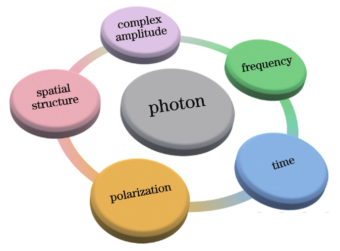
Fig. 1. Basic physical dimension resources of photons

Fig. 2. Methods for vortex beam generation
Fig. 3. Vortex lasers based on discrete components. (a) Polarization vortex laser assisted by conical Brewster prism inserted in cavity[77]; (b) vortex laser based on off-axis coupled ring-shaped pumping[78]; (c) vortex laser based on spin-orbital coupling[79]; (d) vortex laser based on point-defect lens[80]; (e) vortex laser array based on Yb∶YAG/YV4 Raman laser[81]; (f) vortex laser based on metasurface device[82]
Fig. 4. Structural diagram of BG laser[86]
Fig. 5. Output intensity and phase distributions of BG laser based on metasurfaces[86]
Fig. 6. Reconfigurable and tunable OAM laser[87]. (a) Concept and principle; (b) experimental setup
Fig. 7. Experimental results of mode reconfigurable vortex laser[87]. (a) Measured spectra; (b) spectrum of OAM+3 laser; (c) spectrum of OAM-10 laser; (d) intensity profile and interferogram of OAM+3 laser; (e) intensity profile and interferogram of OAM-10 laser
Fig. 8. Experimental results of wavelength tunable vortex laser[87]. (a) Wavelength tunable spectra; (b) spectrum of OAM+1 laser at 1550 nm; (c) spectrum of OAM+1 laser at 1565 nm; (d) intensity profile and interferogram of OAM+1 laser at 1550 nm; (e) intensity profile and interferogram of OAM+1 laser at 1565 nm
Fig. 9. Design of multi-vortex laser[88]. (a) Experimental setup; (b) threshold pump power versus topological charge number of vortex light; (c) image of concentric-ring pattern etched on output coupler; (d) microscopy image of magnified central area
Fig. 10. Information encoding and data transmission based on multi-vortex laser[88]. (a) Experimental setup; (b) multi-vortex light spot pattern and corresponding hexadecimal coding information encoded by DMD; (c) image transfer
Fig. 11. Vortex lasers based on fiber. (a) Low threshold single-wavelength polarization vortex laser based on few-mode FBG[89]; (b) low threshold polarization vortex laser based on long period grating[90]; (c) polarization vortex laser based on pair of few-mode FBGs to realize selective mode operation[91]; (d) high order vortex laser based on ring cavity[92]; (e) vortex femtosecond laser based on mode coupler[93]; (f) vortex laser based on ring-shaped fiber[94]
Fig. 12. Experimental setup of tunable OAM laser[95]
Fig. 13. Transmission spectra[95]. (a) FBG; (b) FPI
Fig. 14. Experimental results of all-fiber wavelength-switchable vortex laser[95]. (a) Measured spectra; (b) measured intensity profiles and interferograms
Fig. 15. Vortex lasers based on integrated devices. (a) Vertical-cavity surface-emitting vortex laser (VCSEL)[96]; (b) vortex laser based on lead bromide perovskite[97]; (c) vortex micro-laser based on InGaAsP/InP platform[98]
Fig. 16. Structural diagrams of micro-cavity lasers[101]. (a) Micro-cavity laser for azimuthally polarized vortex beam; (b) micro-cavity laser for radially polarized vortex beam; (c) cross section of vector laser
Fig. 17. Output light field of vortex laser and light field after transmission through fiber[102]. (a1) Far-field intensity distribution; (b1)-(e1) polarization distributions; (a2) intensity distribution after 2 km fiber transmission; (b2)-(e2) polarization distributions of fiber output field
Fig. 18. Future development trend and prospect of vortex laser

Set citation alerts for the article
Please enter your email address
© Copyright 2018-2021 | Chinese Laser Press. All Rights Reserved 沪ICP备15018463号-20