Polarization holography is a newly researched field, that has gained traction with the development of tensor theory. It primarily focuses on the interaction between polarization waves and photosensitive materials. The extraordinary capabilities in modulating the amplitude, phase, and polarization of light have resulted in several new applications, such as holographic storage technology, multichannel polarization multiplexing, vector beams, and optical functional devices. In this paper, fundamental research on polarization holography with linear polarized wave, a component of the theory of polarization holography, has been reviewed. Primarily, the effect of various polarization changes on the linear and nonlinear polarization characteristics of reconstructed wave under continuous exposure and during holographic recording and reconstruction have been focused upon. The polarization modulation realized using these polarization characteristics exhibits unusual functionalities, rendering polarization holography as an attractive research topic in many fields of applications. This paper aims to provide readers with new insights and broaden the application of polarization holography in more scientific and technological research fields.Polarization holography is a newly researched field, that has gained traction with the development of tensor theory. It primarily focuses on the interaction between polarization waves and photosensitive materials. The extraordinary capabilities in modulating the amplitude, phase, and polarization of light have resulted in several new applications, such as holographic storage technology, multichannel polarization multiplexing, vector beams, and optical functional devices. In this paper, fundamental research on polarization holography with linear polarized wave, a component of the theory of polarization holography, has been reviewed. Primarily, the effect of various polarization changes on the linear and nonlinear polarization characteristics of reconstructed wave under continuous exposure and during holographic recording and reconstruction have been focused upon. The polarization modulation realized using these polarization characteristics exhibits unusual functionalities, rendering polarization holography as an attractive research topic in many fields of applications. This paper aims to provide readers with new insights and broaden the application of polarization holography in more scientific and technological research fields.
Introduction
In traditional holography1, owing to the intensity distribution of two interference waves, including amplitude and phase, being recorded, only the same components of the polarization state of the two interference waves are considered. However, the actual polarization states of the two interference waves are ignored. In contrast, in polarization holography, the amplitude and phase of the two waves as well as the polarization states of the two waves are recorded2-8. For this reason, polarization holography is expected to have more abundant reconstruction characteristics and a wide range of applications.
Polarization holography is a new research field. The previous theory is based on Jones matrix formalism9, wherein the angle between two lights that interfere with each other should be small, and the results are limited under the paraxial approximation10. In the subsequent decades, there have been few reports on this topic. However, since the tensor theory of polarization holography, wherein the response of the recording material to the polarized wave is considered as a tensor, was proposed by K Kuroda11, research on polarized holography has garnered attention, and has made significant progress. D Babara et al. applied the theory to a data storage system and found that the recording density can be increased by modulating the state of polarization12, 13. A Wu et al. discovered the conditions of the null reconstruction effect (NRE) employing circular polarization holography in 2015, wherein no reconstruction wave was observed there even when the Bragg condition was satisfied14. The NRE was experimentally observed by T Todorov et al. in 198615 and theoretically explained by Huang et al. using paraxial coupled mode theory in 199516. S H Lin et al. also observed this phenomenon under a paraxial approximation17, wherein the experiment and theory incorporated a small cross angle between the signal and reference wave, which resulted in the NRE. However, in addition to the small cross angle, certain other factors that resulted in the NRE were determined by X Tan et al. Consequently, the NRE of the polarization hologram was also observed with a large recording angle, successfully overcoming the hinderance encountered owing to the need for paraxial approximation. J Wang et al. analyzed the internal mechanism of NRE and verified the results via experiments in 201618. Subsequently, J Zang et al. and L Shao et al. discovered the conditions of the NRE in linear19 and elliptical20 polarization holography in 2015 and 2019, respectively. The condition of faithful reconstruction effect (FRE), wherein the polarization state of the reconstructed wave is maintained similar to that of the signal wave, is another important research target. In tensor theory, the polarization state of the reconstructed wave is affected by the exposure energy under general conditions. Typically, a balanced exposure condition is used. J Zang21, P Qi22, A Wu14, X Xu23, Y Zhang24, and Z Huang25, 26, detected the balance point by introducing complementary polarization states in the case of linear, circular, and elliptical polarization holography in the period ranging from 2015 to 2021. However, certain problems were encountered and the balance point could not be determined accurately because the condition has a close relationship and setup limitation with the recorded energy and the intersection angle. Consequently, J Y Wang et al. proposed a method for measuring the balance point in 202127, and achieved polarization modulation of the reconstructed wave under unbalanced exposure conditions. However, in certain special cases, the polarization characteristics of the reconstructed wave can be independent of the exposure energy. In 2017, J Zang et al. used a particular crossing angle of 90° with a linearly polarized wave to eliminate the exposure energy requirement19. Y Hong et al. proposed a new method to achieve FRE under an arbitrary crossing angle, and an arbitrary polarization state of the signal28. Between 2020 to 2021, P Qi, Z Huang and J Y Wang studied the FRE that is independent of exposure energy under an interference angle of 90° 29, 30 and arbitrary interference angle31. There have been several applications in this regard. Considering the NRE of linearly polarized wave, which is independent of exposure energy, J Zang successively proposed dual- and four-channel polarization multiplexing methods19, 32, whereas considering the FRE of linearly polarized wave, L Huang proposed a method to generate the vector beams33. Until now, with regard to tensor theory, FRE and NRE of polarization holography with two linear, circular and elliptical polarized waves have been researched. However, the details of their polarization holography behaviors under different polarized states are yet to be analyzed and discussed. Consequently, this paper attempts to analyze and subsequently discuss the reconstruction characteristics of polarization holography recorded by two linearly polarized state waves.
Linear polarization is an essential state, and any complex polarized state can be combined by a linearly polarized state. Many studies on reconstruction characteristics have been reported, for example, the study by S H Lin et al.17, multichannel recording at 90° by J Zang et al.19, 32, and the study of orthogonal reconstruction effect (ORE) by C Wu et al.34. Further, it has also been applied to data storage35-43, and polarization holography for high-density storage for which the representative works are the dual- and four-channel polarization multiplexing scheme proposed by J Zang. The scheme can separate and reconstruct the data pages loaded into the channel by adjusting the polarization state, which deeply taps the value of polarization information of light. In this review, the characteristics and behavior of linear polarization holography have been introduced in detail, including the principle involved and applications.
The rest of the paper has been organized into 3 sections. Section Tensor theory of linear polarization holography introduces the theoretical basis for linear polarization holography and derives the expression of the reconstructed wave. The reconstruction characteristics were divided into two categories according to whether they were affected by exposure energy. Section Reconstruction characteristics independent of exposure energy introduces the reconstruction characteristics that are independent of the exposure energy. By adjusting the polarization state in the polarization holographic recording and reconstruction, the unbalanced influence of the exposure energy on the change in refractive index and the birefringence effect of the polarization-sensitive medium can be eliminated. Further, the polarization characteristics of the reconstructed wave under different interference angles were analyzed. Subsequently, certain applications have been introduced, using FRE, ORE, and NRE to achieve multichannel polarization multiplexing, and to generate vector beams. In polarization multiplexing, the amplitude and phase information of the light can be multiplexed simultaneously. In addition, combining multiplexing technologies, such as angle, shift, and wavelength, can double the density of holographic storage. Thus, by designing the dynamic exposure system, a vector beam with polarization difference distribution can be generated. However, owing to its polarization and phase singularity, a dark hole was observed in the center. Section Reconstruction characteristics related to exposure energy introduces the reconstruction characteristics affected by exposure energy, which have been divided into balanced and unbalanced exposure conditions. Under balanced conditions, certain interesting polarization characteristics have been introduced under different interference angles, whereas, under unbalanced conditions, a method for measuring the exposure response coefficient of polarization-sensitive media has been introduced. Finally, this article provides conclusions and future application prospects.
Tensor theory of linear polarization holography
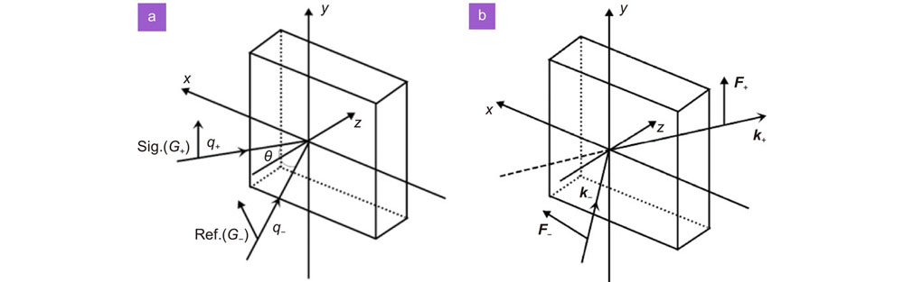
According to the tensor theory of polarization holography, which was proposed by K Kuroda and based on a simple molecular model11, in the recording process, as shown in Fig.1(a), the signal and reference waves interfere with each other, and the interference field can be described as
where G+ and G− are the vector amplitudes, respectively, q+ and q− are the wave vectors of the signal and reference waves, respectively, andr is the position vector. The dielectric tensor of the recording material after exposure can be defined as
where n0 is the refractive index of the material before exposure, and 1 is the unit tensor. Further, scalars A and B are coefficients of photoinduced isotropic and anisotropic refractive index changes in the material, which are correlated to the intensity and polarization grating, respectively, and their values are influenced by the exposure energy21, 27.
In the reconstruction process, as shown in Fig. 1(b), the retrieved reference wave is represented as F−exp(ik−·r), where F− is the vector amplitude and k− is the wave vector of the reading wave. Further, according to the tensor theory of polarization holography11, the reconstructed wave can be represented as
where
k+ is wave vector of the reconstructed wave.
Equations (3) and (4) are only the general expressions for the reconstructed waves by polarization holography, and the physical meaning must be revealed according to the actual polarization state of the waves. In this paper, we discuss the case of a linearly polarized wave only.
Assume that the two orthogonal basic unit vectors of linearly polarized waves are p and s, as shown in Fig. 2. They are perpendicular and parallel to the incident plane, respectively. During the recording and reconstruction process, the signal, reference, and reading waves are linearly polarized wave, and α, β, and γ are the orientation angles between their polarized wave vector directions and p direction, respectively. Therefore, the polarization states can be expressed by the cosine and sine components of thep and s directions, respectively.
Figure 2.The definition of the orientation of the polarized wave under two orthogonal basic unit vectors p and s coordination.
where p+, p− andp'
− are the basic unit p vectors of the signal, reference, and reading waves, respectively, as shown in Fig. 3. These basic unit vectors can be represented as
Figure 3.The definition of basic unit p vectors in the process of (a) recording and (b) reconstruction.
According to the principle of holography, if the Bragg condition is satisfied with the same wavelength during the recording and reconstruction processes, the following equations should also be established:
where θ' and θ are the angles of the signal and reference waves, respectively. Here θ = θ+ + θ−, as shown in Fig. 3. As the basic unit p vector is perpendicular to the wave vector k. Equations (12) and (13) can be transformed into:
where p'
+ is the basic unit p vectors of the reconstructed wave.
Further, the polarization states of the reconstructed wave can be expressed as31:
Equation (16) is the general expression for the waves reconstructed by the polarization holography of full linearly polarized waves. There are two parts in Eq. (16). The first part is the faithful reconstructed wave of the signal G+, whose amplitude is modified by Bcos(β −γ). In contrast, the second part, which is interwoven by all wave components, is the extra content of the reconstructed wave, where the ratio of the dielectric tensor coefficients A to B affects the polarization state of the reconstructed wave, and A/B is defined as the exposure response coefficient27. As the physical meanings and the reconstruction characteristics are not sufficiently clear, they should be discussed from the perspectives of certain special cases of their angles and combinations of each other.
The polarization characteristics of the reconstructed waves were divided into two categories. The first category is the reconstruction characteristics that are independent of the exposure energy, which implies that the polarization state of the reconstructed light is not affected by the exposure energy (A/B=any). In contrast, the second category is the reconstruction characteristics that are related to the exposure energy, that is, the polarization state of the reconstructed wave changes with the exposure energy, and the A/B value is required to satisfy a specific one. The polarization-sensitive media used were all PQ/PMMA (phenanthrenequinone-doped polymethyl methacrylate)44-48 and the optical properties of the materials used in the different experiments varied according to the preparation process.
Reconstruction characteristics independent of exposure energy
The polarization state of the reconstructed wave is independent of the exposure energy. Consequently, its theoretical expression incorporates the s- and p-polarized components in the expression of the reconstructed wave with the same dielectric tensor coefficients A and B. To identify its physical properties, three cases were considered: θ =90°, θ =0°, and 0° < θ < 90°.
θ = 90°
When the interference angle is 90°, the FRE or NRE independent of the exposure energy can be realized under the most relaxed conditions by the reconstructed wave. Further, the interesting reconstruction characteristics can be applied to multichannel polarization multiplexing to generate vector beams. The applications related to these characteristics have been described in section Application. However, only cubic materials can be used to satisfy the requirement of a 90° interference angle, which is caused by the refractive index of the PQ/PMMA material (n=1.492). Under this condition (θ = 90°), Eq. (16) becomes
Herein, the reconstructed wave consists of two parts: the signal component and the s-polarized component affected by the exposure energy (A + B) and polarization angle. Till one among the signal, reference, and reading waves comprises only a p-polarized component, or the signal wave is s-polarized, a faithful reconstructed wave of the signal G+ can be obtained. The reconstruction characteristics of this case are summarized in Table 1.
Table Infomation Is Not Enable
Among these polarization characteristics, the s- and p-polarized components in the expression of the reconstructed wave consist of the same dielectric tensor coefficient, thereby rendering FRE independent of the exposure energy31. Further, the amplitude of the reconstructed wave is affected by the polarization angles of the reference and reading waves; if the two are the same, the amplitude of the reconstructed wave is the largest, while the amplitude is the smallest when their states are orthogonal to each other. In particular, NRE that is independent of exposure energy can be realized when pure p-polarized waves are present in the signal, reference, and reading waves, respectively (rows 2, 3, and 4 in Table 1)29, 49. The NRE was verified by J Zang19, 32 through an experiment, wherein the hologram was recorded at an interference angle of 90° by p-polarized signal and reference waves. Consequently, the hologram was read using a linearly polarized wave with a polarization angle of 0–360°, and the data obtained are shown in Fig. 4.
Figure 4.The relationship between NDE and the polarization angle of reading wave. The double arrow symbol represents the polarization angle of reading wave. Figure reproduced with permission from ref.32, The Optical Society.
As shown in Fig. 4, the normalized diffraction efficiency (NDE) attains a maximum value for reading wave polarization angles of 0°, 180°, or 360° (p-polarized). In contrast, minimum value is obtained at 90° or 270° (s-polarized). In addition, the ratio of the maximum to the minimum value of the NDE is SNR = 64:1. Furthermore, the NRE of linear polarization holography was verified in this experiment.
In 2020, P Qi verified the FRE and NRE of a signal wave with an arbitrary polarization angle at 90° interference angle29, and the effect of the polarization angle of reading wave on the reconstructed wave is illustrated in Fig. 5. The parameters β and α that were used in their study have the same meaning as α and γ in this paper. In the experiment, the signal waves with different polarization angles were used (three cases are introduced in this paper: α = 0°, 45°, and 90°), and the reference wave was p-polarized (β = 0°).
Figure 5.The variation of NDE and polarization angle of the reconstructed wave with the polarization angle of reading wave under different recording conditions. The polarization angles of the signal wave are: 0°, 45° and 90°, respectively. (a) The variation of NDE of reconstructed wave. The theoretical value is cos2γ curve. (b) The variation of polarization angle of the reconstructed wave. Figure reproduced with permission from ref.29, Chinese Laser Press.
The results show that for the reading wave with an arbitrary polarization angle, the NDE was related to the polarization angle of the reading wave and proportional to the value of cos2γ (Fig. 5(a)). NRE was realized when the reading wave was orthogonal to the reference wave. Moreover, as shown in Fig. 5(b), FRE can be realized under a reading wave with an arbitrary polarization angle. The conclusion arrived by P Qi is consistent with that of row 3 in Table 1.
θ = 0°
When the interference angle is 0°, the reconstructed wave can obtain the highest diffraction efficiency, and no NRE exists. Simultaneously, FRE or ORE independent of the exposure energy can be achieved under the relatively relaxed conditions. Moreover, these reconstruction characteristics can still be applied to polarization multiplexing, resulting in advantages in miniaturized optical devices because the interference angle between the signal and reference path is zero36, 37, 50, 51.
Under this condition (θ = 0°), the two beams are coaxial, and Eq. (16) becomes
On analyzing Eq. (18), the expression of the reconstructed wave is found to be complex, which is the coupling state of the signal, reference, and reading waves. However, polarization modulation that is independent of exposure energy can be achieved by controlling the polarization state for recording and reconstruction. Therefore, under the condition of coaxial recording, the reconstructed wave follows these laws.
When the polarization angle of the signal, reference, and reading waves satisfy a special relationship (same or orthogonal), as shown in Table 2, the reconstruction wave can achieve FRE or ORE that is independent of the exposure energy. Consequently, with an aim to arrive at the conclusions in Table 2, we conducted simulations, focusing on the variation of the polarization angle and NDE of the reconstructed wave with the polarization angle of the reading wave. The simulation results are shown in Fig. 6.
Table Infomation Is Not Enable
Figure 6.The simulated value of reconstructed wave changes with the polarization angle of reading wave under different recording conditions. All the polarization angles of the reference wave are p-polarized. (a) The variation of polarization angle of the reconstructed wave. (b) The variation of NDE of the reconstructed wave.
As shown in Fig. 6, when the polarization angle of the reference wave is orthogonal to that of the signal wave (red line), the polarization angle (Fig. 6(a)) and NDE (Fig. 6(b)) of the reconstructed wave exhibited a linear change under the reading wave with different polarization angles. Moreover, this linear change is independent of the exposure energy. In such recording conditions, FRE or ORE can be realized as long as the polarization angle of the reading wave is the same or orthogonal to that of the reference wave. This result is the same as that in rows 1 and 2 in Table 2.
The blue line in Fig. 6 represents another situation, that is, the polarization angle of the signal wave is the same as that of the reference wave. Under these conditions, the polarization angle (Fig. 6(a)) and NDE (Fig. 6(b)) of the reconstructed wave exhibited a nonlinear change owing to the change in the polarization angle of the reading wave. Further, two exposure conditions were simulated (A/B=10, A/B=0.3), and it was found that the linear change was related to the exposure energy (A/B). In a similar manner, FRE or ORE can still be achieved when the polarization angle of the reading wave is the same or orthogonal to that of the reference wave, which is the same as that in rows 3 and 4 of Table 2.
0° < θ < 90°
When the interference angle is between 0° and 90°, NRE that is independent of the exposure energy does not exist. Moreover, strict conditions must be satisfied for the reconstruction wave to achieve FRE or ORE that is independent of exposure energy, and simultaneously, the polarization and interference angles must be constrained. The conditions required to achieve FRE or ORE under a general interference angle are listed in Table 331.
Table Infomation Is Not Enable
To realize FRE or ORE independent of the exposure energy, the four conditions listed in Table 3 must be satisfied. Further, the polarization angle of the reading wave should also satisfy the corresponding conditions. When θ = 90°, the conditions required for faithful reproduction in Table 3 are consistent with those in Table 1, and the ORE in Table 3 becomes NRE. In contrast, for θ = 0°, the conditions required for FRE and ORE in Table 3 are consistent with those in Table 2. Thus, it can be concluded that Table 3 reflects the general laws of the conditions required for FRE, ORE, and NRE independent of exposure energy in linear polarization holography. J Y Wang verified the conclusion of FRE at a 40° interference angle31, 52 and the experimental data are shown in Fig. 7. In the experiment, a signal wave with polarization angles of 60° and 120° was used, while the reference and reading waves had the same polarization angles. The polarization angles of the reference and reading waves were changed simultaneously (0–180°) for multiple experiments, wherein every 10° polarization angle was changed into an unexposed area on the PQ/PMMA material. The parameters γ, α, and β used in their study have the same meanings as α, β, and γ used in this paper.
Figure 7.The variation of polarization angle of the reconstructed wave with the polarization angle of reference and reading waves. Figure reproduced with permission from ref. 31, The Optical Society.
In Fig. 7, it can be observed that when the reconstructed wave achieves FRE, the polarization angles of the reference and reading waves correspond to the theoretical values calculated in Table 3. Consequently, this experimental conclusion proves that in a polarization-sensitive medium, for a fixed interference angle, there always exists two reading waves with different polarization angles, which can result in the reconstructed wave achieving FRE independent of the exposure energy. The ORE of a polarization hologram in special cases was studied by C Wu34 and verified for various interference angles (θ = 15.8°, 26.2°, 38.1°, and 58.5°). In the experiment, the signal wave was s-polarized, while the reference wave was p-polarized. Figure 8 shows the changes observed in the s- and p-polarized components in the reconstructed wave with the polarization angle of the reading wave under various interference angles. The parameters of α used in their study is the same as γ used in this paper.
Figure 8.The variation of the s- and p-polarized components in the reconstructed wave with the HWP2 angle under different interference angles.The interference angles are 15.8°, 26.2°, 38.1° and 58.5°, respectively, which are distinguished by lines of different colors. The polarization angle of the reading wave is twice the fast-axis angle of HWP2. Figure reproduced with permission from ref. 34, Chinese Laser Press.
In Fig. 8, it can be observed that when the fast-axis angle of HWP2 is 45°, 135°, 225°, or 315° (the reading wave is s-polarized), the normalized power of the s-polarized component in the reconstructed wave is the lowest, while that of the p-polarized component is the highest, thereby indicating that the ORE was realized. Further, the normalized power of the ORE was found to be inversely proportional to cos2θ. Thus, these phenomena conform to the ORE law listed in Table 3.
We now discuss the polarization characteristics of the reconstructed waves that are independent of the exposure energy under various interference angles. Among them, FRE can be realized at any interference angle. In contrast, the ORE can be realized at an interference angle other than 90°, while the NRE can only be realized at an interference angle of 90°. Moreover, the FRE condition at a 90° interference angle was observed to be the most relaxed, and the underlying cause of this phenomenon is the NRE at an interference angle of 90°. That is, the NRE can be superimposed with FRE without affecting the polarization state of the reconstructed wave, which consequently increases the degree of freedom of the conditions required to realize FRE. Furthermore, the diffraction efficiency of the reconstructed wave produced by ORE was found to decrease with an increase in the interference angle, attaining the lowest value at an interference angle of 90 °, that is, NRE occurs.
Application
Polarization multiplexing
Polarization multiplexing technology implies that the amplitude, phase, and polarization information recorded in the material can be selectively read via the adjusting of the polarization state of the reading wave. This technology can be applied to holographic storage35-37, 53-61, modulation of amplitude19, 32, and phase50, 62-69. Moreover, combining polarization multiplexing with angle13, 17, 70-74, shift75-77 or wavelength78-80 multiplexing can result in a further increase in the density of holographic storage. From the perspective of polarization holography, multichannel polarization multiplexing technology utilizes the FRE12, 13, 81, 82, ORE, and NRE17, 19, 32, 83 mechanism in polarization holography. Thus, we now introduce polarization multiplexing technology using FRE or ORE. The scheme is presented in Table 4, wherein the amplitude information of the reconstructed wave is determined by the signal wave.
Table Infomation Is Not Enable
As shown in Table 4, the FRE is employed for recording the intensity and polarization holograms at the same position on a polarization-sensitive medium. In the reconstruction process, two holograms were read using an s-polarized wave, and subsequently, the two recorded holograms were faithfully reconstructed. The amplitude information of the respective signal waves are carried by the s- and p-polarized components in the reconstructed wave. Thereafter, the two types of amplitude information can be separated using PBS to realize the dual-channel effect. The researches of D Barda and T Ochiai are based on this effect12, 13, as well as for the dual-channel polarization multiplexing implemented by C Li and W D Koek using circularly polarized waves81, 82. Consequently, the ORE can be used to achieve a similar dual-channel multiplexing technology provided the reading wave is p-polarized. Regarding the method using FER or ORE polarization multiplexing can be achieved only if the intensity and polarization holograms in the reconstructed wave are separated. This offers the advantage of the ability to change the interference angle, and the highest diffraction efficiency can be obtained under the coaxial interference condition, which is conducive to improving the SNR36, 37. However, in general, the induced refractive index change of the intensity hologram is greater than the birefringence effect of the polarization hologram (A/B>−1)21, 27, which implies that the reconstructed image quality of the intensity hologram is better than that of the polarization hologram. This phenomenon was observed in the research of D Barda12. To solve this problem, in 2017, J Zang proposed a pure polarization holographic dual-channel polarization multiplexing scheme based on the NRE of linearly polarized wave19. The experimental scheme is presented in Table 519.
Table Infomation Is Not Enable
For convenience, the physical symbols were unified. The symbols US, UR, F, and UF used by J Zang19 represent the signal wave G+, reference wave G−, reading wave F−, and reconstructed wave F+, respectively, while the symbols α and β represent the dielectric tensor coefficients A and B, respectively. All the amplitude information of the reconstructed wave originates from the signal wave.
As shown in Table 5, two orthogonal polarization holograms are recorded at the same position as that of the PQ/PMMA material. When the reading wave is s-polarized, the first hologram obtained is NRE, whereas the second hologram is FRE, which carried the amplitude information of the second hologram. The first hologram can be extracted separately when the reading wave is p-polarized. This scheme offers the advantage of presenting two reconstructed images with the same dielectric tensor coefficient, implying that the two holograms can obtain the same NDE when they are being reconstructed. The experimental device used for polarization multiplexing is shown in Fig. 9. In a similar manner, owing to the NRE of circularly polarized waves, polarization multiplexing can be realized at an interference angle of 0°14. Therefore, in these research17, 83, recording two orthogonal circularly polarized holograms under the condition of paraxial approximation can aid in the realization of dual-channel polarization multiplexing technology. Moreover, the principle of dual-channel polarization multiplexing is the same as that of linear polarization holography.
Figure 9.Optical setup of linear polarization holography. SF, spatial filter; PBS, polarization beam splitter; SH, shutters; HWP, half-wave plates. Figure reproduced with permission from ref.19, The Optical Society.
In the experiment, the wavelength of the laser used was 532 nm and the cubic PQ/PMMA material was used with a bottom surface of 10 mm ×10 mm. Further, the interference angle was 90°. In addition, in the recording stage, the signal wave used in the first hologram was s-polarized, while the reference wave was p-polarized. Whereas, in the second hologram, the polarization states of the signal and reference waves were interchanged. Further, in the reconstruction process, two holograms were irradiated with a reading wave that satisfied Bragg conditions, and the generated reconstructed wave was split by PBS2 and consequently captured by two PMs. By changing the polarization angle of the reading wave (0–360°), the data obtained are shown in Fig. 10.
Figure 10.The variation of the s- and p-polarized components in the reconstructed wave with the HWP1 angle. Figure reproduced with permission from ref.19, The Optical Society.
The first hologram was s-polarized in the reconstructed wave (Zang's article mistakenly considered it as second hologram). The NDE attained a maximum value when the reading wave was in the vicinity of 0°, 180°, and 360° (p-polarized), and a minimum value when the reading wave was approximately 90° or 270° (s-polarized). In contrast, the second hologram was p-polarized, and its corresponding changes were opposite to that of the first hologram; that is, when the NDE of one hologram was the largest, for the other hologram it was the smallest, thereby realizing the dual-channel function of polarization multiplexing. In addition, the best SNR was approximately 18∶1, which was attained when the polarization angle of the reading wave was 180°.
Based on the conclusion of the dual channel results, in 2019, J Zang proposed a four-channel polarization multiplexing technology. The four-channel method is also based on the NRE of linear polarization holography. This scheme is presented in Table 632.
Table Infomation Is Not Enable
As shown in Table 6, J Zang used an interference angle of 90°, and the four holographic channels used were Hn (n=1, 2, 3, 4). First, the amplitude data pages were loaded into the signal waves of channels H1 and H2, and subsequently, the s-polarized reference wave was used to simultaneously record two pages of orthogonally polarized amplitude data. Thereafter, the polarization state of the reference wave was changed to the p-polarized and the amplitude data of two pages of orthogonal polarization to record channels H3 and H4. When the reading wave was s-polarized, channels H3 and H4 realized NRE, while channels H1 and H2 realized FRE. At this point, all the p-polarized component in the reconstructed wave originated from channel H1, whereas all the s-polarized waves originate from channel H2. Thus, using this special phenomenon, the amplitude information carried by channels H1 and H2 can be distinguished using the PBS. Further, when the reading wave was p-polarized, channels H1 and H2 realized NRE, whereas channels H3 and H4 realized FRE. Herein, the amplitude information carried by channels H3 and H4 can still be distinguished using the PBS. Further, using this scheme, four-channel polarization multiplexing can be realized. The experimental device using this experimental scheme is shown in Fig. 11.
Figure 11.Optical setup for four-channel polarization holographic recording. SF, spatial filter; PBS, polarization beam splits; SH, shutters; HWP, half-wave plates; BS, beam splitter; SLM, spatial light modulator. Figure reproduced with permission from ref.32, The Optical Society.
As shown in Fig. 11, J Zang used an interference angle of 90° and the laser wavelength was 532 nm. The laser was divided into a signal path (s-polarized) and a reference wave (p-polarized) through PBS1. Further, the signal wave was divided into two orthogonal polarization channels using PBS2. The SLMs were placed in the two orthogonal polarization channels to load the amplitude information, while the HWP3 was adjusted to render the two channels of equal intensity. Consequently, in the experiment, HWP2 was adjusted to make the reference wave s-polarized, as shown in Fig. 12(a) and 12(b), and the A and B patterns were loaded on SLM1 and SLM2 in the signal path, respectively. Subsequently, after combining through the BS, the first hologram was recorded with the reference wave of s-polarized in PQ/PMMA. Thereafter, the reference wave was p-polarized, as shown in Fig. 12(c) and 12(d), and the C and D patterns were loaded on SLM1 and SLM2 in the signal path, respectively. The second hologram was recorded at the same position using the same operation. The experimental data are shown in Fig. 12.
Figure 12.Images reconstructed in four-channel holographic image recording. (a–d) Original transmitted images before holographic recording. (e) and (f) reconstructed image of the p-polarized reading wave. (g) and (h) reconstructed image of the s-polarized reading wave. Figure reproduced with permission from ref.32, The Optical Society.
The experimental results are shown in Fig. 12(e–h). Patterns A and B were received on CMOS1 and CMOS2 when reading the two holograms using the s-polarized wave, respectively. In contrast, when reading with p-polarized, the A and B patterns disappeared, and C and D patterns were received on CMOS1 and CMOS2, respectively. The contrast of the reconstructed B pattern was found to be lower than that of the recorded pattern when compared with the image before reconstruction, as shown in Fig. 12(a–d). This is because pattern B is an intensity hologram while the patterns A, C, and D are polarization holograms. Consequently, the difference in diffraction efficiency between the two types of holograms caused the B pattern to be overexposed21, 27. J Zang recorded two holograms at the same position as the PQ/PMMA material, which included four different amplitude data pages. Thus, by changing the polarization state of the reading wave, four data pages with different amplitudes can be separated and reconstructed. In addition, the reconstructed image exhibited high fidelity and good contrast and can be used for holographic storage, thereby realizing four-channel polarization multiplexing technology.
Vector beams
Vector beams have been used in many fields, including data storage84-86, optical manipulation87-89, and optical communications90, 91. Common methods employed for generating vector beams include q-plate92, 93, optical fiber94, 95, and spatial light modulator96. Next, we introduce a simple low-cost method to generate the vector beams. Based on the conclusions of P Qi29, L Huang et al. proposed a new method to generate vector beams in 202133, designed a dynamic exposure system to successfully record, and read out the vector beams in a cubic PQ/PMMA material using the FRE of linear polarization. The device that generates the vector beams is shown in Fig. 13.
Figure 13.Schematic of experiment.PBS, polarization beam splitter; M, mirror; P, polarizer; HWP, half wave plate; L, lens. Figure reproduced with permission from ref.33, The Optical Society.
The experiment uses a laser with a wavelength of 532 nm, and the beam is divided into signal (s-polarized) and reference (p-polarized) paths following its passage through the PBS. The interference angle between the signal and reference waves was 90°, and the intensities were 1 mW and 500 μW, respectively. In the signal path, the dynamic exposure system comprised an HWP and an angle aperture of 0.2°. Further, the polarization angle of the linearly polarized wave that passed through the angle aperture was changed by rotating the HWP. Thus, with the rotation of the angular aperture (0–360°), the vector beam was gradually recorded in the PQ/PMMA material. During the recording process, the polarization angle of the signal wave constantly changed, while the reference wave was fixed to p-polarized. Whereas, during the reconstruction process, a p-polarized reading wave was used to illuminate the hologram and the generated vector beam was received by CMOS. It is evident from Table 1 and the conclusions of P Qi29 that under these recording and reconstruction conditions, the signal wave can be faithfully reproduced for any polarization angle. Therefore, in theory, with the rotation of the HWP and angle aperture, the various polarization states after passing through the angle aperture can be recorded in PQ/PMMA and subsequently faithfully reconstructed. The recording time was defined as the time required for the angle aperture to rotate by 360°. In the experiment, the order of the vector beams recorded in the PQ/PMMA material can be changed by controlling the relative rotation speed of the HWP and angle aperture, which is expressed as33:
where θp is the polarization angle after passing through the angle aperture,m is the order of the vector beams, θH is the polarization angle after the HWP, and θ0 is a constant that describes the initial polarization state at θH=0. To generate m-order vector light, the rotation speed of the HWP must be m/2 times that of the angle aperture. Thus, using this method, L Huang recorded and reconstructed the first- and second-order vector beams in PQ/PMMA bulk material (this article introduces the second-order vector beams).
The second-order vector beams can be obtained when the rotating speed of the HWP is the same as that of the angle aperture (speed: 1°/s). The intensity and polarization distributions of the reconstructed wave are shown in Fig. 14.
Figure 14.The intensity and polarization distributions of the vector beams with azimuthal index of m=2, θ0=30°. (a–e) The simulation of reconstructed wave intensity distribution after changing the transmission axis of polarizer (30°, 120°, 150°, 180°). (f–j) The corresponding experimental results. Figure reproduced with permission from ref.33, The Optical Society.
A polarization singularity can be observed at the center of the beam for the vector beams, and the field intensity distribution of the field is annular97. As shown in Fig. 14(f), the intensity distribution of the reconstructed wave obtained from the experiment was consistent with the simulated value. Further, as evident in Fig. 14(g–j), the polarization characteristics of the vector beams were tested by adding P3 to the reconstructed path, and the beams was divided into four lobes. The higher the order, the more lobes, and the corresponding experimental results are consistent with the simulated values. Thus, this experiment indicates that use of polarization holography to record and generate a vector beam in a polarization-sensitive medium is feasible.
Reconstruction characteristics related to exposure energy
As discussed previously, certain polarization characteristics of reconstructed wave are independent of the exposure energy. However, in general, the polarization state of the reconstructed wave is affected by the exposure energy. In the expression of the reconstructed wave, as expressed in Eq. 16, the dielectric tensor coefficients A and B are the values related to the exposure energy. Thus, upon confirmation of the recording and reconstruction conditions, the polarization state of the reconstructed wave can be determined by the value of A/B. Further, balanced or unbalanced exposure conditions can be used to realize the polarization modulation of the reconstructed wave.
Balanced condition
The balanced condition is
Equation (20) indicates that the contribution of the intensity hologram to the reconstructed wave is equal to that of the polarization hologram. However, these contributions depend on the material, intensity, and exposure energy. When Eq. (20) is satisfied, Eq. (16) can be simplified as
where G'
+ is the orthogonal state of the signal wave. This result indicates that a new linearly polarized state is reconstructed. In 2014, J Zang studied this and explained the influencing factors of reaching a balanced condition of exposure21. In the experiment, the laser wavelength was 532 nm, and the interference angle was 41°. Further, both the reference and reading waves were s-polarized, and the signal wave adopted three types of linearly polarized waves with polarization angles of 90°, 0°, and 45°, respectively. The experimental data are shown in Fig. 15.
Figure 15.Experimental results.(a) Signal wave is s-polarized. (b) Signal wave is p-polarized. (c) Signal wave is 45°-polarized. All reference and reading waves are s-polarized. Notice that the vertical scale in different graphs is different. Figure reproduced with permission from ref.21, The Springer Nature.
Figure 15(a) and 15(b) exhibit pure intensity and pure polarization holograms, respectively. Certain obvious differences exist between the two holograms, which is the primary reason why achieving FRE of reconstructed wave under normal condition is a challenge. Further, it is also the primary reason for the difference in the quality of reconstructed images of different channels in polarization multiplexing12, 32. As shown in Fig. 15(c), when the polarization angle of signal wave is 45°, both the intensity and the polarization holograms contribute to the reconstructed wave. However, the difference in intensity and polarization holograms causes the s-polarized component in the reconstructed wave to be larger than the p-polarized component, thereby rendering the realization of the FRE a challenge. J Zang highlighted that the reason for the huge difference in PQ/PMMA film is the difference between the two types of photo-induced effects: induced refractive index change and birefringence. The intensity hologram is affected by the effect of induced refractive index change (Fig. 15(a)). In contrast, the polarization hologram is affected by the birefringence effect (Fig. 15(b)). Consequently, K Kuroda proposed that when the two effects are balanced, the polarization state of the signal wave can be correctly reconstructed. As shown in Fig. 15(c), when the exposure energy is approximately 11 J/cm2, the s-polarized component is equal to the p-polarized one. Moreover, the two photo-induced effects are balanced, and the theoretical expression in the tensor polarization holography is A/B=–1. Thus, this experiment demonstrates that one of the ways to achieve FRE involves controlling the exposure energy to balance the two effects.
In the case of the balanced condition of exposure, the polarization characteristics of the reconstructed wave follow the same law at various interference angles. The reconstructed wave is expressed as Eq. (21). Further, the FRE, ORE, and NRE are all determined by the polarization state of the reference and reading waves, which are unrelated to the polarization state of the signal wave. Thus, the interference angle only affects the diffraction efficiency of ORE.
In Table 7, in the case of the balanced condition of exposure, the reconstructed wave can realize FRE when the polarization angle of the reading wave is the same as that of the reference wave. In contrast, when the polarization angle of the reading wave is orthogonal to that of the reference wave, the reconstructed wave can realize ORE in the case of non-orthogonal interference (θ ≠ 90°), and can achieve NRE in the case of orthogonal interference (θ = 90°). Further, the diffraction efficiency of ORE is inversely proportional to the interference angle. Thus, in the case of the balanced condition of exposure, the reconstructed wave exhibits certain interesting reconstruction characteristics, which can be utilized for applications in the field of optical functional devices98-101. Consequently, we divided it into three cases: θ = 90°, θ = 0°, and 0° < θ < 90°.
Table Infomation Is Not Enable
θ = 90°
In the case of the balanced conditions of exposure and 90° interference angle, the polarization angle of the reconstructed wave is not related to the reading wave, and has the same polarization angle as that of the signal wave. However, the diffraction efficiency of the reconstructed wave is affected by the polarization angle of the reading wave, which results in the NRE of the reconstructed wave.
When the interference angle is 90°, only the first term in Eq. (21), remains. On replacing G+ with its components form we obtain
To visually analyze the reconstruction characteristics, Eq. (22) was simulated. Figure 16 presents the results, which was obtained for simulation at a 90° interference angle using a signal wave with a 60° polarization angle and a p-polarized reference wave.
Figure 16.Simulated variation of NDE of reconstructed wave with polarization angle of reading wave. (a) The variation of the s- and p-polarized components in the reconstructed wave with polarization angle of reading wave. (b) The variation of the polarization angle of reconstructed wave with polarization angle of reading wave.
In Fig. 16(a), the NDE of the reconstructed wave can be observed to be the highest when the polarization angle of the reading wave is the same as that of the reference wave. However, when their polarization angles are orthogonal to each other, the amplitude of the reconstructed wave is zero (NRE). The s- and p-polarized waves exhibit a trend similar to the polarization angle of the reading wave, and the ratio of s- to p-polarized waves is always equal to 3, which ensures that the polarization angle of the reconstructed wave is always at 60° (Fig. 16(b)). These phenomena conform to those presented in Table 7. Further, the hologram formed under this condition has the same function as the polarizer.
θ = 0°
Under balanced conditions of exposure and 0° interference angle, the diffraction efficiency of the reconstructed wave is the highest and remained unchanged. The sum of the polarization angles of the reconstructed and reading waves is a fixed value.
As cosθ = 1, the Eq. (21) can be transformed to22
The result shows that a new linearly polarized state is reconstructed, and the polarization angle is α+β−γ, which was performed by P Qi22. The results indicate that the sum of the polarization angles of the reconstructed and reading waves is a fixed value, and that the amplitude of the reconstructed wave is a constant. P Qi had highlighted that at an interference angle of 0°, the reconstructed wave satisfies Eq. (23) under any exposure condition, when the polarization state of the signal wave is orthogonal to that of the reference wave; this phenomenon is shown in Fig. 6. In a similar manner, the Eq. (23) was simulated at a 0° interference angle using a signal wave with a 60° polarization angle and a p-polarized reference wave. The results are presented in Fig. 17.
Figure 17.Simulated variation of NDE of reconstructed wave with polarization angle of reading wave. (a) The variation of the s- and p-polarized components in the reconstructed wave with polarization angle of reading wave. (b) The variation of the polarization angle of reconstructed wave with polarization angle of reading wave.
When the reconstructed wave realizes FRE or ORE, the law followed is consistent with that presented in Table 7. Further, the NDE of the reconstructed wave remains unchanged when the polarization angle of the reading wave changes. However, simultaneously, the polarization angle of the reconstructed wave exhibited a linear change. Consequently, the hologram formed under this condition has the same function as the half-wave plates.
0° < θ < 90°
When θ is between 0° and 90°, there is no change in Eq. (21), FRE and ORE can be achieved, and no NRE occurs. However, the reconstruction characteristics of the reconstructed wave, such as the NDE and polarization angle, are both affected by the polarization angle of the reading wave and present a nonlinear change. Consequently, Eq. (21) was simulated at a 40° interference angle using a signal wave with a 60° polarization angle and a p-polarized reference wave. The results are presented in Fig. 18.
Figure 18.Simulated variation of NDE of reconstructed wave with polarization angle of reading wave. (a) The variation of the s- and p-polarized components in the reconstructed wave with polarization angle of reading wave. (b) The variation of the polarization angle of reconstructed wave with polarization angle of reading wave.
As shown in Fig. 18(a), in general, changing the polarization angle of the reading wave causes a simultaneous change in the polarization angle and the NDE of the reconstructed wave, resulting in peak dislocation of the s- and p-polarized components in the reconstructed wave. As discussed earlier, when the reading wave has the same polarization angle as that of the reference wave, the NDE of the reconstructed wave obtained is the highest, and FRE can be realized. In contrast, when orthogonal, the NDE obtained is the lowest, and ORE can be realized. Further, as shown in Fig. 18(b), the polarization angle of the reconstructed wave changes nonlinearly.
Unbalanced condition
In our earlier discussions, we introduced certain interesting polarization characteristics in the case of balanced conditions. However, the most common exposure conditions were in an unbalanced state. To realize polarization modulation of the reconstructed wave in the case of unbalanced conditions, the exposure response coefficient (A/B) of the polarization-sensitive medium must be measured. Thus, we analyze this aspect. The unbalanced condition is:
In an unbalanced condition of exposure, the diffraction efficiency of the intensities and polarization holograms in the reconstructed wave are different. In 2021, J Y Wang proposed a method for measuring the exposure response coefficient A/B27. Consequently, the variation of the exposure response coefficient of PQ/PMMA material with exposure energy was tested using this method, and the NRE with non-orthogonal polarization reading was realized. In the experiment, both the reference and reading waves were s-polarized. Signal waves with different polarization angles were used for several experiments (0°, 15°, 30°, 45°, 60°, 75°, and 90°). Under such recording and reading conditions, according to Eq. (16), the expression of the exposure response coefficient A/B is27:
where χ is the polarization angle of the reconstructed wave. The experimental results are presented in Fig. 19.
Figure 19.The variation of reconstructed wave with exposure energy under different recording conditions. (a) The variation of polarization angle of reconstructed wave with exposure energy, where polarization angles of signal wave are 0°, 15°, 30°, 45°, 60°, 75°, and 90°. (b) The variation of exposure response coefficient A/B with exposure energy for different linearly polarized signal wave, where polarization angles of signal wave are 15°, 30°, 45°, 60°, 75°. Figure reproduced with permission from ref.27, The Optical Society.
As shown in Fig. 19(a), under different recording conditions, the polarization angle of the reconstructed wave varied with the exposure energy. Thus, considering the data of the polarization angle of the reconstructed wave and Eq. (25), the variation in the exposure response coefficient with exposure energy can be obtained. As shown in Fig. 19(b), the exposure response coefficient A/B changes with the increase of exposure energy, and exhibits a different trend under signal waves with different polarization angles, with the variation range being 0.3–8.7. However, at the beginning of the exposure, the A/B under different recording conditions had approximately the same initial value (8.4). In contrast, when the exposure energy was lower than 140 J/cm2, the average value of A/B decreased from 8.4 to 3.1. During this period, the change rule of A/B was almost independent of the polarization angle of the signal wave indicating that at the initial stage of exposure, the intensity and polarization holograms of PQ/PMMA materials encounter difficulties on attaining the balanced condition of exposure (A/B≠–1) under any recording conditions, and they are in an unbalanced condition. Concurrently, different recording conditions have almost no effect on this unbalanced state. Based on this special phenomenon, J Y Wang used an unbalanced condition (A/B=8.4) to realize the NRE of non-orthogonal linear polarization holography. The method uses the condition of A/B=8.4 to make the s- and p- polarized components equal to zero in Eq. (16). Consequently, the diffraction efficiency of the reconstructed wave varied with the exposure energy, as shown in Fig. 20.
Figure 20.The variation of diffraction efficiency with exposure energy.Figure reproduced with permission from ref.27, The Optical Society.
As shown in Fig. 20, the maximum diffraction efficiency was 0.005 at exposure energy of 800 J/cm2. Such a low diffraction efficiency indicates that the reconstructed wave realized NRE. In a similar manner, this also proves that the measured exposure response coefficient A/B value is accurate. This experiment relies on the exposure response coefficient to achieve NRE in the state of non-orthogonal interference, recording, and reading. Thus, this conclusion is expected to break through the limitation of a 90° interference angle, and polarization multiplexing dual- and four-channel technology can be realized under general interference angles.
Conclusion and outlook
In linear polarization holography, we focused on the changes in the polarization state and NDE of the reconstructed wave, including FRE, ORE, and NRE. Among the reconstruction characteristics that are independent of exposure energy, the polarization characteristics change linearly with the exposure energy, which is achieved by constraining the polarization state during the holographic recording and reconstruction process. In general, the polarization characteristics of the reconstructed wave are affected by the exposure energy and present a nonlinear change. Combined with these reconstruction characteristics, multichannel polarization multiplexing technology or vector beam generation can be carried out. However, these applications are still in the preliminary stage, which combination with phase modulation can be further studied for improving storage capacity, or generating vector beams with phase vortices. Moreover, the reconstructed wave exhibits linear polarization characteristics in the case of a special conditions (θ = 0° or 90°,A/B = –1), and nonlinear characteristics under general conditions (0° < θ < 90°, A/B ≠ –1). These can provide references in the analysis of hologram noise or the characteristics of polarization and diffraction efficiency of holographic gratings36, 37, 102, 103. In addition, it is expected to make metamaterials with anisotropic refractive index distribution through multiple exposure, realizing the modulation of the amplitude, phase, polarization and propagation direction of light, which can allow potential applications such as optical metasurfaces, photonic crystal, all-optical logic gate, polarization sensor and so on. Consequently, it is conducive to the production of linear and nonlinear optical functional devices with low-cost planar structures, and planar optical elements with a customer-design function are possible owing to its properties. In terms of theoretical research, the changes of rotation direction and ellipticity of circularly or elliptically polarized waves in polarization holography are complex, and accompanied by some special reconstruction characteristics24. Therefore, the research of elliptical polarization holography is challenging. At present, the main challenge comes from the polarization sensitive media. Looking for a material with high diffraction efficiency for polarization holograms, which simultaneously has stable optical properties, ideal absorption and transmission coefficients, as well as low volume shrinkage is the basis for the application of polarization holography.
We are grateful for financial supports from National Key R&D Program of China (2018YFA0701800), and Project of Fujian Province Major Science and Technology (2020HZ01012).
The authors declare no competing financial interests.
References
[9] Nikolova L, Ramanujam PS. PolarizationHolography (Cambridge University Press, Cambridge, 2009).
[49] Zang JL. Fundamental research on polarization holography based on tensor theory (Beijing Institute of Technology, Beijing, 2017).