• Chinese Optics Letters
  • Vol. 16, Issue 6, 062801 (2018)
Shaofu Xu, Weiwen Zou*, Guang Yang, and Jianping Chen
Author Affiliations
  • State Key Laboratory of Advanced Optical Communication Systems and Networks, Shanghai Institute for Advanced Communication and Data Science, Department of Electronic Engineering, Shanghai Jiao Tong University, Shanghai 200240, China
  • show less
    DOI: 10.3788/COL201816.062801 Cite this Article Set citation alerts
    Shaofu Xu, Weiwen Zou, Guang Yang, Jianping Chen. Ultra-high range resolution demonstration of a photonics-based microwave radar using a high-repetition-rate mode-locked fiber laser[J]. Chinese Optics Letters, 2018, 16(6): 062801 Copy Citation Text show less
    Experimental configuration of the photonics-based microwave radar. AMLL, actively mode-locked laser; AWG, arbitrary waveform generator; PS, power divider; MZM, Mach–Zehnder modulator; PD, photodetector; BPF, bandpass filter; LNA, low-noise amplifier; TA, transmitting antenna; RA, receiving antenna; PC, personal computer.
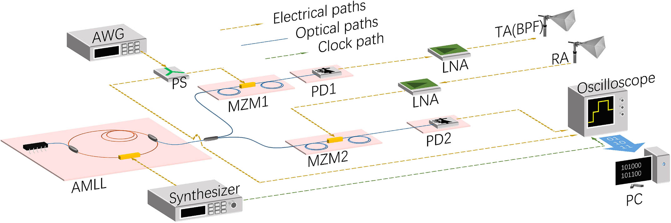
    Fig. 1. Experimental configuration of the photonics-based microwave radar. AMLL, actively mode-locked laser; AWG, arbitrary waveform generator; PS, power divider; MZM, Mach–Zehnder modulator; PD, photodetector; BPF, bandpass filter; LNA, low-noise amplifier; TA, transmitting antenna; RA, receiving antenna; PC, personal computer.
    Single cycle of the baseband LFM pulse. (a) The waveform in the time domain and (b) the STFT spectrum. The applied bandwidth is 8 GHz.
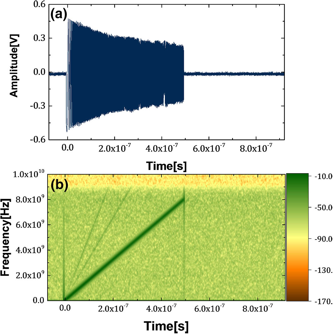
    Fig. 2. Single cycle of the baseband LFM pulse. (a) The waveform in the time domain and (b) the STFT spectrum. The applied bandwidth is 8 GHz.
    Pulse compression range profile with or without the MLS algorithm. The applied bandwidth is 3 GHz. (a) The simulation result with different α. (b) The experimental result. The generated broadband signal is processed when α = 0.92. The amplitude is normalized in dB. Alpha represents α in Eq. (1).
    Fig. 3. Pulse compression range profile with or without the MLS algorithm. The applied bandwidth is 3 GHz. (a) The simulation result with different α. (b) The experimental result. The generated broadband signal is processed when α = 0.92. The amplitude is normalized in dB. Alpha represents α in Eq. (1).
    (a) Pulse compression range profile when different bandwidths are applied to the radar. The power is normalized. (b) The range resolution versus different bandwidths. The red curve is the experimental results and the blue dashed curve is the theoretical calculation. The MLS algorithm is applied to both.
    Fig. 4. (a) Pulse compression range profile when different bandwidths are applied to the radar. The power is normalized. (b) The range resolution versus different bandwidths. The red curve is the experimental results and the blue dashed curve is the theoretical calculation. The MLS algorithm is applied to both.
    Pulse-compressed range profile of detecting two neighboring targets. Targets are placed line by line and separated by about 6 cm. (a)–(h) correspond to different bandwidths from 1 GHz to 8 GHz. The amplitude is normalized. BW, bandwidth.
    Fig. 5. Pulse-compressed range profile of detecting two neighboring targets. Targets are placed line by line and separated by about 6 cm. (a)–(h) correspond to different bandwidths from 1 GHz to 8 GHz. The amplitude is normalized. BW, bandwidth.
    Shaofu Xu, Weiwen Zou, Guang Yang, Jianping Chen. Ultra-high range resolution demonstration of a photonics-based microwave radar using a high-repetition-rate mode-locked fiber laser[J]. Chinese Optics Letters, 2018, 16(6): 062801
    Download Citation