State Key Laboratory of Advanced Optical Communication Systems and Networks, Shanghai Institute for Advanced Communication and Data Science, Department of Electronic Engineering, Shanghai Jiao Tong University, Shanghai 200240, China
Shaofu Xu, Weiwen Zou, Guang Yang, Jianping Chen, "Ultra-high range resolution demonstration of a photonics-based microwave radar using a high-repetition-rate mode-locked fiber laser," Chin. Opt. Lett. 16, 062801 (2018)
Copy Citation Text
We experimentally demonstrate the ultra-high range resolution of a photonics-based microwave radar using a high repetition rate actively mode-locked laser (AMLL). The transmitted signal and sampling clock in the radar originate from the same AMLL to achieve a large instantaneous bandwidth. A Ka band linearly frequency modulated signal with a bandwidth up to 8 GHz is successfully generated and processed with the electro-optical upconversion and direct photonic sampling. The minor lobe suppression (MLS) algorithm is adopted to enhance the dynamic range at a cost of the range resolution. Two-target discrimination with the MLS algorithm proves the range resolution reaches 2.8 cm. The AMLL-based microwave-photonics radar shows promising applications in high-resolution imaging radars having the features of high-frequency band and large bandwidth.
After several decades of development, next-generation radar systems have marched toward higher range and azimuthal resolution, software-defined multiband agility, and higher mobility. Increase of the working or carrier frequency is a promising way to reduce the volume of antennas and enhance the azimuthal resolution. Furthermore, the large bandwidth at high-frequency bands offers an opportunity to reach a high range resolution[1,2]. Electronic components suffer the well-known problem of noisy performance at high frequencies and electronic or microwave signal processing like up- and down-conversions conspicuously deteriorates the signal quality, especially when the high-frequency band is desired[3]. In contrast, microwave photonics techniques nowadays provide a new path to break through the electronic problems[4,5]. Ultra-large bandwidth and low noise features of photonics guarantee the generation of broadband microwave signals at a high frequency with low noise[6,7]. In microwave photonic detection, the precise optical pulse train is easily used as a high-speed sampling clock so that the sampling process can be carried out without noisy down-conversion mixing[8,9].
To take the advantages of photonics into radar systems, work was done with various architectures and schemes[10–18]. Heterodyning and dispersion techniques make significant use of the ultra-wide band of photonics, reaching very high resolutions[12]. But they are limited in radar applications because of the lack of coherence. To highly exploit the coherent property of photonics, a fully photonics-based coherent radar is systematically proposed and demonstrated[10,11]. In their works, a passively mode-locked laser (MLL) at the repetition rate of 400 MHz is used as a coherent source. It offers both upconversion signals and a sampling clock. By appropriate filtering, low-noise microwave signals at X and/or S bands are chosen to work for the detection of moving targets and landform delineating. They have made sufficient use of the low-noise feature of photonics and have attained a spurious free dynamic range of 50 dB in the receiving process. However, the range resolution is about 4 m[11] and is in principle limited by the repetition rate (i.e., 400 MHz) of the MLL.
In this Letter, the ultra-high range resolution of a photonics-based microwave radar using an actively mode-locked laser (AMLL) is experimentally demonstrated. In the radar configuration, an AMLL with a high repetition rate serves as the coherent source to offer the optical pulse train for both the signal generation and the sampling clock. Multiple coherent optical modes of AMLL guarantee that the generated microwave signal can work at a very high frequency band with low timing jitter. Here, the Ka band () is chosen for operation. Moreover, the large free spectral range of the AMLL enables the radar to achieve a large instantaneous bandwidth and ultra-high range resolution. In order to utilize the high-resolution ability for real scenarios, the minor lobe suppression (MLS) algorithm is applied for a better dynamic range when detecting neighboring targets. A high range resolution of 2.8 cm is experimentally demonstrated to discriminate two neighboring targets with a distance of 6 cm.
Sign up for Chinese Optics Letters TOC. Get the latest issue of Chinese Optics Letters delivered right to you!Sign up now
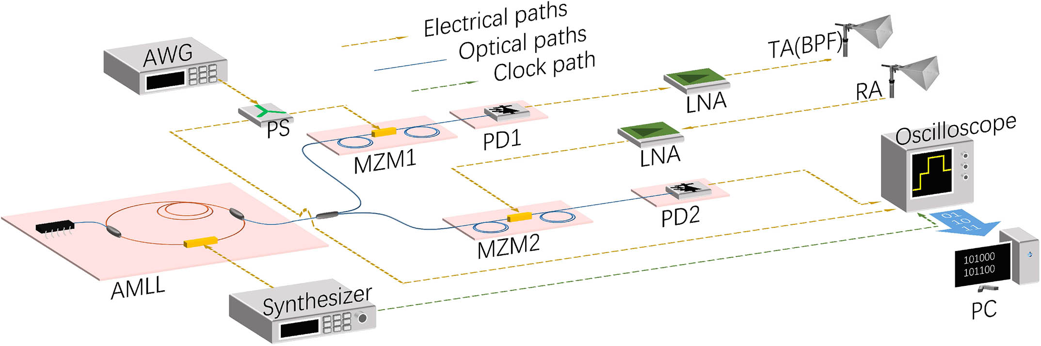
Figure 1 depicts the photonics-based microwave radar configuration. The optical pulse train from an AMLL (Calmar PSL-10-TT) with a repetition rate of 20 GHz is divided into two paths. One path is sent to the transmitter for radar signal generation and the other goes to the receiver working as the sampling clock in the receiver. In the transmitter, a high-speed Mach–Zehnder modulator (MZM1, Photoline Ltd., MXIQ-LN-40) is used to modulate the optical pulse train via an linearly frequency modulated (LFM) microwave signal pulse, which is generated by an arbitrary waveform generator (AWG, Keysight Ltd., M9502 A). In the receiver, another high-speed Mach–Zehnder modulator (MZM2, Photoline Ltd., MXIQ-LN-40) is utilized to sample the received echoes. The bandwidths of both the MZM1 and MZM2 are 40 GHz so that they are sufficient for signal modulation and sampling at the Ka band. Referring to the principle described in Ref. [10], the achievable bandwidth of the radar is half the repetition rate of the optical pulse train, which is 10 GHz in this study. When the modulated optical pulse train travels through the high-speed photodetector (PD1, U2t Ltd., XPDV2150R) with a 50 GHz bandwidth, a series of broadband microwave signals with different center frequencies can be generated. The frequencies are multiple times the AMLL repetition rate (20 GHz). The transmitting antenna (TA, A-INFOMW Ltd., LB-28-25-C2) and the same type of antenna in the receiving antenna (RA) have the 13.5 GHz bandwidth from 26.5 GHz to 40 GHz, which can effectively act as a bandpass filter (BPF) at the Ka band. The low-noise amplifiers (LNAs, Connphy microwave Inc., CLN-26G40G-3030-K) with a gain of 30 dB are employed before the TA and after the RA, respectively. In the receiver, the optical pulse train sampling echo is sent to PD2 (Discovery Ltd., DSC-R412-39-FC) with a bandwidth of 20 GHz to recover the baseband signal of the radar. The oscilloscope (Keysight Ltd., DSO-S) with a bandwidth of 8 GHz works as a low-pass filter and digitizes the baseband signal. Note that the oscilloscope is synchronized to the synthesizer in sampling process. The digitized data is processed via a personal computer (PC).
Figure 1.Experimental configuration of the photonics-based microwave radar. AMLL, actively mode-locked laser; AWG, arbitrary waveform generator; PS, power divider; MZM, Mach–Zehnder modulator; PD, photodetector; BPF, bandpass filter; LNA, low-noise amplifier; TA, transmitting antenna; RA, receiving antenna; PC, personal computer.
In principle, the instantaneous bandwidth could reach 10 GHz in the AMLL-based radar. However, due to the limited bandwidth of the oscilloscope (8 GHz), we carried out the experiment with the bandwidths up to 8 GHz. The linearly frequency modulated pulse generated by the AWG is sent to the MZM1 as the radar’s baseband signal. Its parameters are set as follows: the LFM frequency range is 0–8 GHz, the center frequency is 4 GHz, the period is 1 μs, and the duty-cycle ratio is 50%. A copy of the LFM pulse is directly recorded by the oscilloscope and utilized as the reference for the pulse-compression signal processing of the received echoes[13]. A single cycle of the LFM pulse that is generated by the AWG and recorded by the oscilloscope is depicted in Fig. 2(a). Figure 2(b) shows its short-time Fourier transform (STFT) and indicates that the LFM pulse has reached the bandwidth of 8 GHz.
Figure 2.Single cycle of the baseband LFM pulse. (a) The waveform in the time domain and (b) the STFT spectrum. The applied bandwidth is 8 GHz.
In real radar application scenarios, multiple neighboring targets appear simultaneously so that the pulse compression minor lobes will significantly deteriorate target discriminating. We adopt an MLS algorithm into the pulse compression signal processing via a Hamming window function in the frequency domain[2]. The Hamming window function is described by where is a parameter determining the suppression effect, represents the frequency, and is the applied bandwidth. Figure 3 illustrates the simulation and experimental results of the MLS algorithm on the broadband signal. Applying different of the MLS, the minor lobes are suppressed by different levels and the range profiles are fattened differently. From the simulation results illustrated in Fig. 3(a), we can see that with , the minor lobes are suppressed by 28 dB compared to the main lobe and the range resolution is deteriorated by 1.47 times. This is a relatively efficient parameter because a small cannot suppress the minor lobes sufficiently and a large one deteriorates the range resolution too heavily. In the experiment, the same minor lobe suppression effect with is also indicated in Fig. 3(b). It seems that the fluctuations of curves come from laboratory clutter and environmental noise rather than minor lobes. With the effective MLS algorithm in the digital signal processing, we can get a better MLS ratio and a higher dynamic range, although it sacrifices to some extent the range resolution, which is the basic requirement of the radar system applied to the imaging application to detect and process a lot of neighboring targets.
Figure 3.Pulse compression range profile with or without the MLS algorithm. The applied bandwidth is 3 GHz. (a) The simulation result with different . (b) The experimental result. The generated broadband signal is processed when . The amplitude is normalized in dB. Alpha represents in Eq. (1).
In principle, the range resolution of the LFM radar can be expressed as[1]where is range resolution, is the light speed in vacuum, represents the applied bandwidth, and is the deteriorating factor related to the MLS parameter. In the case of , .
Keeping the center frequency of the LFM pulse signal (4 GHz) unchanged while setting its bandwidth to be different, we characterize the corresponding range resolution that is illustrated in Fig. 4. According to the pulse compression range profile in Fig. 4(a), the larger the bandwidth, the narrower the compressed pulse. The range resolution can be extracted by reading half the normalized amplitude. Note that the MLS algorithm with the same parameters as Fig. 3(b) is adopted to all the profiles in Fig. 4(a). Figure 4(b) summarizes the characterized range resolution as a function of the bandwidth. The nominal range resolution defined in Eq. (2) is theoretically estimated and compared in Fig. 4(b). As can be seen, the experimentally measured range resolution reduces reciprocally with the increase of the bandwidth, matching the theoretical estimation. It is noticeable that when the bandwidth is low (about lower than 5 GHz), the experimental results are larger than the theoretical ones. This is because the power reflected from clutter in the laboratory also contributes to the power peak in the range profile along with the target when the range resolution is not high enough. It turns out to be the fattened range profile and deteriorates the range resolution. When the bandwidth is high enough, the experimentally measured range resolutions more closely fit the theoretical estimations. When the bandwidth is 8 GHz, the broadest bandwidth in this study, the range resolution reaches 2.8 cm. It verifies that, with the proposed photonics-based microwave radar system, a high range resolution can be attained by modulating the Ka band carrier with the broadband signal.
Figure 4.(a) Pulse compression range profile when different bandwidths are applied to the radar. The power is normalized. (b) The range resolution versus different bandwidths. The red curve is the experimental results and the blue dashed curve is the theoretical calculation. The MLS algorithm is applied to both.
Moreover, we experimentally demonstrate the ability of the proposed radar in multitarget detection. Two identical reflectors are set line by line and about 9.4 m away from the antennas. Figure 5 depicts the experimental results when the applied bandwidth is changed from 1 GHz to 8 GHz. The distance between two reflectors is set to be about 6 cm. Note that when the bandwidth is low, the radar system cannot attain a range resolution high enough to discriminate them. The pulse compression only gives a merged detecting result. From Fig. 4(b), only when the bandwidth is larger than 5 GHz, the radar can realize the range resolution of 6 cm and thus two targets are discriminated. This is a proof-of-concept demonstration of detecting multiple targets. As long as two neighboring targets are clearly discriminated, it is possible to image complex objects with the help of additional azimuth changes or ISAR techniques[14,16–18].
Figure 5.Pulse-compressed range profile of detecting two neighboring targets. Targets are placed line by line and separated by about 6 cm. (a)–(h) correspond to different bandwidths from 1 GHz to 8 GHz. The amplitude is normalized. BW, bandwidth.
In summary, we have experimentally demonstrated the ultra-high range resolution of a photonics-based microwave radar using AMLL. In the radar configuration, an AMLL is applied as a coherent source to provide an optical pulse train not only with a high stability and precision but also with a high repetition rate, allowing the modulation of basebands with large bandwidths. Utilizing the optical pulse train as a radio frequency upconvertor as well as a sampling clock, we generated a Ka band LFM signal with a large bandwidth and finished the echo receiving and processing. For a better dynamic range, we have adopted a digital signal processing of the MLS algorithm with appropriate parameters. Experimental results show that the AMLL-based radar reaches a range resolution up to 2.8 cm with the MLS algorithm, i.e., 1.9 cm without the MLS algorithm. The proof-of-concept experiment was carried out to demonstrate the ability of the radar to detect multiple targets. The experimental results show that the radar can discriminate targets with a high range resolution and a high minor lobe suppression rate. It is worth noting that when a high-speed oscilloscope is used as a digitizer then the sampling rate is limited in the radar receiver. If a multichannel photonic analog-to-digital converter is adopted for direct sampling of the radar signal, then the demand on electrical digitizers[19,20] will be reduced. Therefore, this photonics-based microwave radar using AMLL could provide a large bandwidth, ultra-high range resolution, and multiple-band operation agility.
References
[1] M. I. Skolnik. Introduction to Radar Systems, 2nd edition(1980).
[2] D. R. Wehner. High Resolution Radar(1987).
[3] V. Ravenni. Proceedings of the European Microwave Conference, 1718(2007).
[4] J. Company, D. Novak. Nat. Photonics, 1, 330(2007).
Shaofu Xu, Weiwen Zou, Guang Yang, Jianping Chen, "Ultra-high range resolution demonstration of a photonics-based microwave radar using a high-repetition-rate mode-locked fiber laser," Chin. Opt. Lett. 16, 062801 (2018)