• Laser & Optoelectronics Progress
  • Vol. 58, Issue 23, 2314005 (2021)
Yan Liu1, Pengshuai Liu1, Yang Guo1, Zongjin Li1, Qinglin Zhang2, Linjie Zhang1, and Jianxun Zhang1、*
Author Affiliations
  • 1College of Materials Science and Engineering, Xi'an Jiaotong University, Xi'an , Shaanxi 710049, China
  • 2Ningxia Vovational Technical College of Industry and Commerce, Yinchuan , Ningxia 750021, China
  • show less
    DOI: 10.3788/LOP202158.2314005 Cite this Article Set citation alerts
    Yan Liu, Pengshuai Liu, Yang Guo, Zongjin Li, Qinglin Zhang, Linjie Zhang, Jianxun Zhang. Dilution Rate of Laser Cladded Ultrahigh Strength Steel[J]. Laser & Optoelectronics Progress, 2021, 58(23): 2314005 Copy Citation Text show less
    Diagram of laser cladding
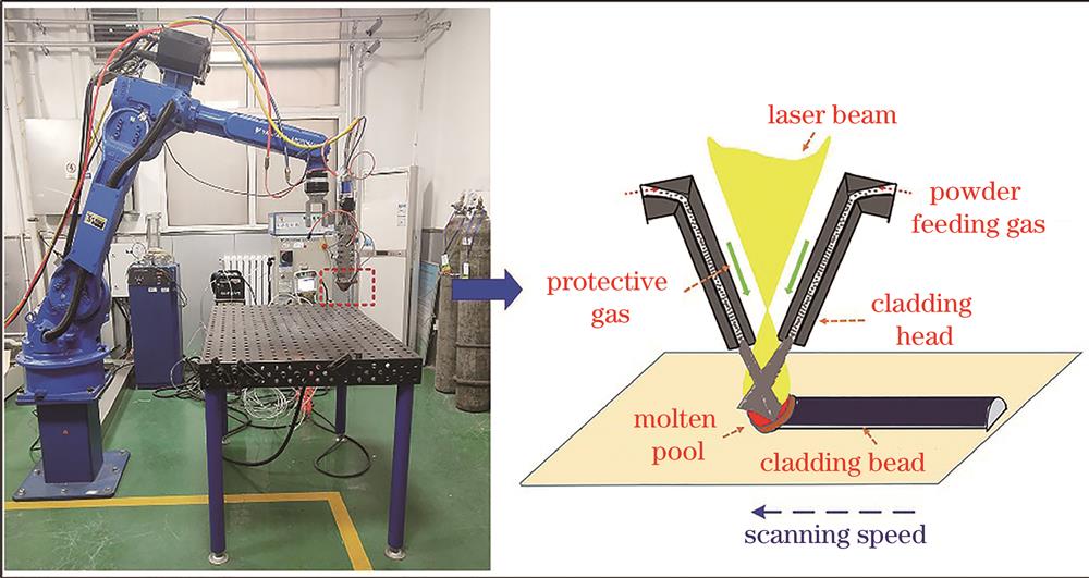
    Fig. 1. Diagram of laser cladding
    Schematic of micro-shear experimental apparatus
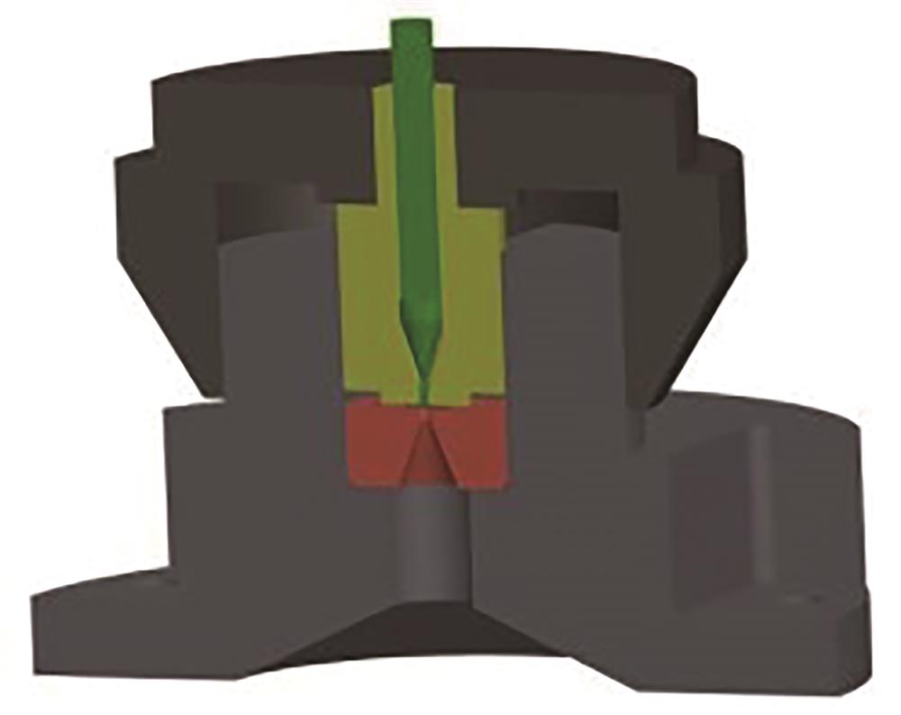
    Fig. 2. Schematic of micro-shear experimental apparatus
    Main parameters related to cladding layer cross-section
    Fig. 3. Main parameters related to cladding layer cross-section
    Cladding tracks formed at constant powder heat absorption rate and variable scanning rates as well as constant scanning rate and variable powder heat absorption rates
    Fig. 4. Cladding tracks formed at constant powder heat absorption rate and variable scanning rates as well as constant scanning rate and variable powder heat absorption rates
    Geometrical morphologies of cladding bead cross-section formed at constant powder heat absorption rate and variable scanning rates
    Fig. 5. Geometrical morphologies of cladding bead cross-section formed at constant powder heat absorption rate and variable scanning rates
    Variations of cross-section size of cladding bead formed at constant powder heat absorption rate and variable scanning rates
    Fig. 6. Variations of cross-section size of cladding bead formed at constant powder heat absorption rate and variable scanning rates
    Microhardness distribution of cladding beads formed at constant powder heat absorption rate and variable scanning rates
    Fig. 7. Microhardness distribution of cladding beads formed at constant powder heat absorption rate and variable scanning rates
    Geometrical morphologies of cladding bead cross-section formed at constant scanning speed and variable powder heat absorption rates
    Fig. 8. Geometrical morphologies of cladding bead cross-section formed at constant scanning speed and variable powder heat absorption rates
    Variations of cross-section size of cladding bead formed at constant scanning speed and variable powder heat absorption rates
    Fig. 9. Variations of cross-section size of cladding bead formed at constant scanning speed and variable powder heat absorption rates
    Microhardness distribution of cladding bead formed at constant scanning speed and variable powder heat absorption rates
    Fig. 10. Microhardness distribution of cladding bead formed at constant scanning speed and variable powder heat absorption rates
    Microshear test results with and without dilution rate. (a) Microshear test points; (b) tested interface bonding strength and shear strength
    Fig. 11. Microshear test results with and without dilution rate. (a) Microshear test points; (b) tested interface bonding strength and shear strength
    ElementCNiCrSiBVFe
    Mass fraction /%0.122.4616.870.770.640.22Bal.
    Table 1. Chemical composition of new martensitic stainless steel 12Cr17Ni2B
    ElementCNiCrSiVMnCuMoFe
    Mass fraction /%0.38-0.431.65-2.00.70-0.951.45-1.800.05-0.100.60-0.90≤0.350.30-0.50Bal.
    Table 2. Nominal composition of 300M steel
    Constant powder heat absorption rateConstant scanning rate
    No.Power /kWPowder feed rate /(g·min-1Scanning rate /(mm·min-1No.Power /kWPowder feed rate /(g·min-1Scanning rate /(mm·min-1
    R11.713.1350P11.1
    R2420P21.2
    R3840P31.2513.11680
    R41260P41.3
    R51680P51.4
    R62100P61.5
    R72520
    R82940
    Table 3. Single factor experimental process parameters
    No.Process parameterGeometrical size
    Power /kWPowder feed rate /(g·min-1Scanning rate /(mm·min-1Tc /μmW /μmContact angle /(°)Tp /μmW/TcAp /(Ac+Ap) /%
    R11.713.13501708.83182.540.1778. 61.95.9
    R24201533.03349.242.2742.92.214.2
    R3840890.12865.136.1635.73.219.4
    R41260620.92317.529.2550.03.721.4
    R51680461.52159.527.2414.34.725.9
    R62100362.62119.826.7400.05.826.7
    R72520335.22150.827.1378. 66.436.5
    R82940274.71793.722.6342. 96.529.5
    Table 4. Geometrical sizes of cladding bead formed at constant powder heat absorption rate and variable scanning rates
    No.Process parameterGeometrical size
    Power /kWPowder feed rate /(g·min-1Scanning rate /(mm·min-1Tc /μmW / μmContact angle /(°)Tp /μmW /TcAp /(Ac+Ap) /%
    P11.113.11680351.91506.241.5365.24.31.9
    P21.2309.51660.745.0324.65.411.9
    P31.25333.31801.343.5352.45.411.5
    P41.3333.51816.138.2324.55.423.7
    P51.4375.01694.456.8303. 64.526.0
    P61.5386.11879.736.3342.24.920.5
    Table 5. Geometrical size of cladding bead cross-section formed at constant scanning speed and variable powder heat absorption rates
    Yan Liu, Pengshuai Liu, Yang Guo, Zongjin Li, Qinglin Zhang, Linjie Zhang, Jianxun Zhang. Dilution Rate of Laser Cladded Ultrahigh Strength Steel[J]. Laser & Optoelectronics Progress, 2021, 58(23): 2314005
    Download Citation