• Chinese Optics Letters
  • Vol. 18, Issue 3, 031301 (2020)
Xinyi Wang, Gangqiang Zhou, Zhengtao Jin, Liangjun Lu, Guiling Wu, Linjie Zhou*, and Jianping Chen
Author Affiliations
  • State Key Laboratory of Advanced Optical Communication Systems and Networks, Shanghai Key Laboratory of Navigation and Location Services, Shanghai Institute for Advanced Communication and Data Science, Department of Electronic Engineering, Shanghai Jiao Tong University, Shanghai 200240, China
  • show less
    DOI: 10.3788/COL202018.031301 Cite this Article Set citation alerts
    Xinyi Wang, Gangqiang Zhou, Zhengtao Jin, Liangjun Lu, Guiling Wu, Linjie Zhou, Jianping Chen. Wavelength-mode pulse interleaver on the silicon photonics platform[J]. Chinese Optics Letters, 2020, 18(3): 031301 Copy Citation Text show less
    Schematic structures of (a) the TDM interleavers in parallel and serial configurations, (b) the WDM interleaver, and (c) the MDM interleaver.
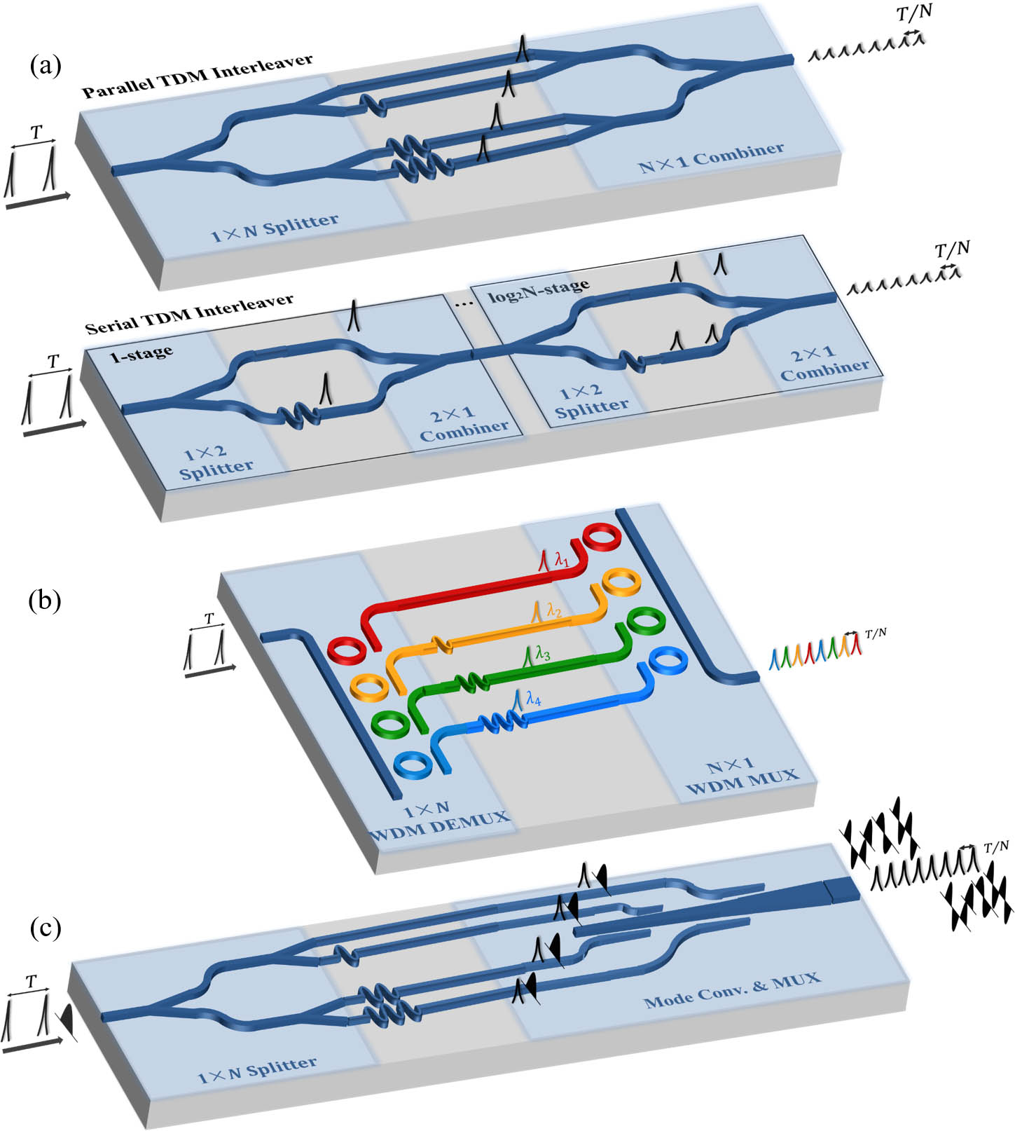
    Fig. 1. Schematic structures of (a) the TDM interleavers in parallel and serial configurations, (b) the WDM interleaver, and (c) the MDM interleaver.
    (a) Schematic structure of a wavelength-mode interleaved photonic signal processing system. (b) The structure of the wavelength demultiplexer based on two-stage cascaded Mach–Zehnder interferometers. (c) The structure of the mode converter and multiplexer.
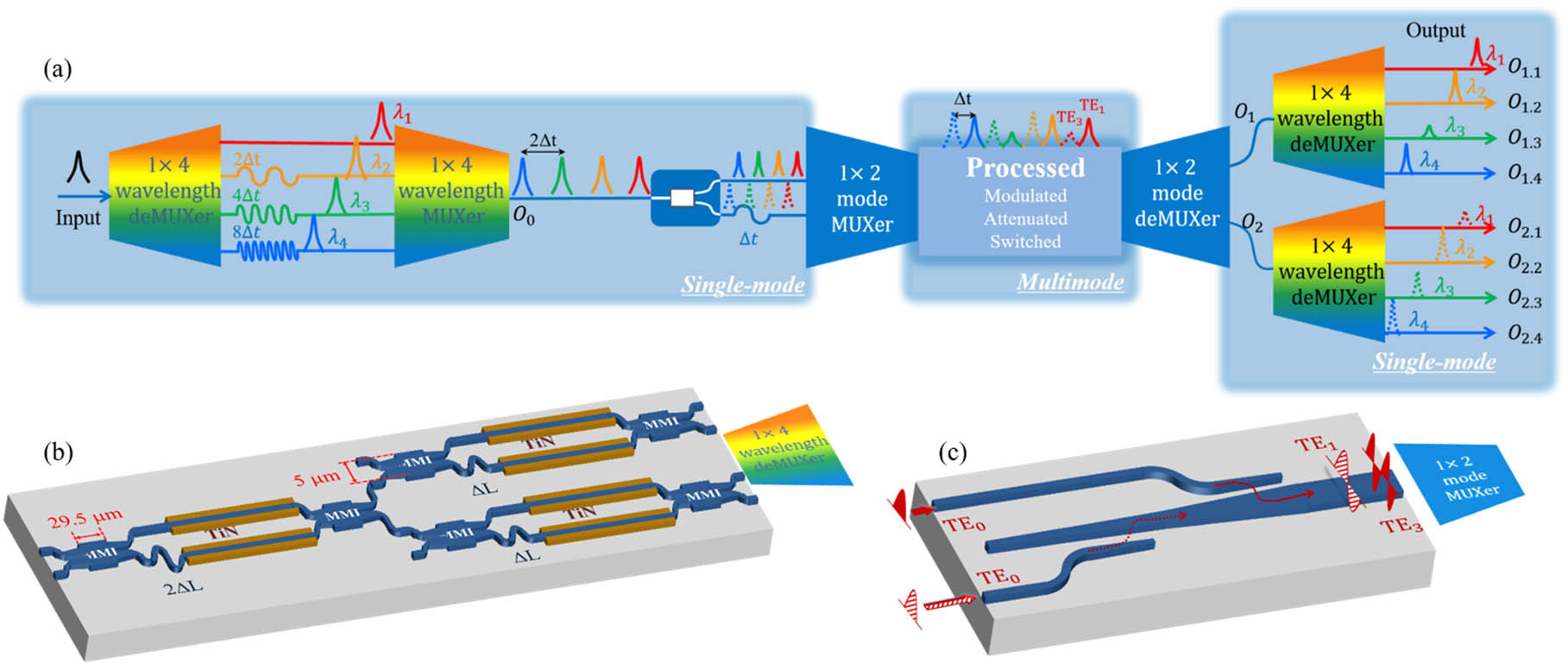
    Fig. 2. (a) Schematic structure of a wavelength-mode interleaved photonic signal processing system. (b) The structure of the wavelength demultiplexer based on two-stage cascaded Mach–Zehnder interferometers. (c) The structure of the mode converter and multiplexer.
    (a) Optical microscope image of the fabricated chip. (b) A photo of the packaged chip with fiber array coupling and electrical wire-bonding to a PCB.
    Fig. 3. (a) Optical microscope image of the fabricated chip. (b) A photo of the packaged chip with fiber array coupling and electrical wire-bonding to a PCB.
    (a) The transmission spectra of the 1×4 wavelength demultiplexer. (b) The transmission spectrum of the wavelength-division interleaver. (c) (left) The optical pulse waveforms at the end of the wavelength-division interleaver. (right) The delay error of the optical pulses. The red color indicates the measured pulses and the green color indicates the ideal pulses with a time interval of 250 ps.
    Fig. 4. (a) The transmission spectra of the 1×4 wavelength demultiplexer. (b) The transmission spectrum of the wavelength-division interleaver. (c) (left) The optical pulse waveforms at the end of the wavelength-division interleaver. (right) The delay error of the optical pulses. The red color indicates the measured pulses and the green color indicates the ideal pulses with a time interval of 250 ps.
    (a) The transmission spectra from output ports O1,1, O1,2, O1,3, and O1,4 through TE1 mode transmission in the multimode waveguide. (b) The transmission spectra from output ports O2,1, O2,2, O2,3, and O2,4 through TE3 mode transmission in the multimode waveguide. (c) (left) The optical pulse waveforms at the end of the wavelength-mode-division interleaver. Dotted curves: the optical pulse through the TE1 mode; solid curves: the optical pulse through the TE3 mode. (right) The delay error of the optical pulses. The red color indicates the measured pulses and the green color indicates the ideal pulses with a time interval of 125 ps.
    Fig. 5. (a) The transmission spectra from output ports O1,1, O1,2, O1,3, and O1,4 through TE1 mode transmission in the multimode waveguide. (b) The transmission spectra from output ports O2,1, O2,2, O2,3, and O2,4 through TE3 mode transmission in the multimode waveguide. (c) (left) The optical pulse waveforms at the end of the wavelength-mode-division interleaver. Dotted curves: the optical pulse through the TE1 mode; solid curves: the optical pulse through the TE3 mode. (right) The delay error of the optical pulses. The red color indicates the measured pulses and the green color indicates the ideal pulses with a time interval of 125 ps.
    Multiplexing methodsIntegration platformAccount of channelsDelay step (ps)Delay error (%)Intrinsic loss* (dB)
    Parallel-TDM[9]Silicon8259
    Serial-TDM[12]Silica2410012
    Serial-TDM[26]InP223.16
    Serial-TDM[25]Silicon27103
    WDM[3]Silicon4253.80.350
    WDM+MDMOur work81253.20
    Table 1. Performance Comparison of Several Typical Integrated Pulse Interleavers
    Xinyi Wang, Gangqiang Zhou, Zhengtao Jin, Liangjun Lu, Guiling Wu, Linjie Zhou, Jianping Chen. Wavelength-mode pulse interleaver on the silicon photonics platform[J]. Chinese Optics Letters, 2020, 18(3): 031301
    Download Citation