
Yuandong Jia, Jia Qiang, Liang Zhang, Jianjun Jia. Spaceborne Long-Distance Tracking Method Based on Adaptive Vibration Suppression[J]. Acta Optica Sinica, 2020, 40(22): 2212003
- Acta Optica Sinica
- Vol. 40, Issue 22, 2212003 (2020)
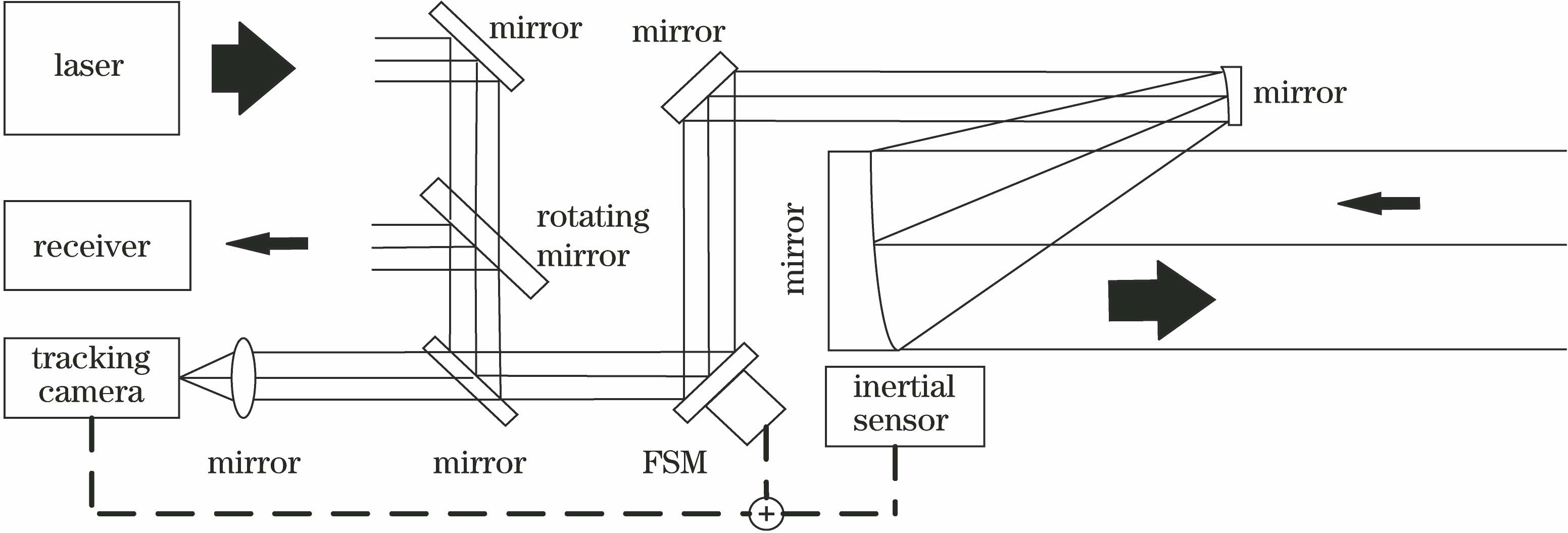
Fig. 1. Structural diagram of laser ranging and tracking system
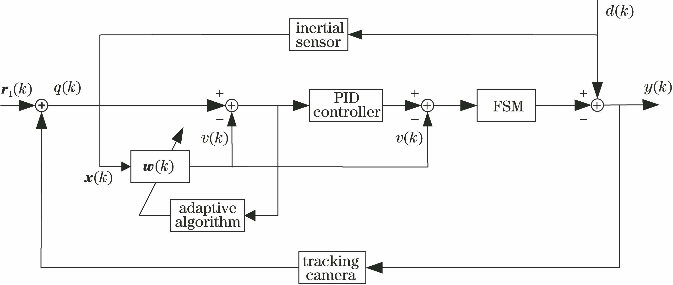
Fig. 2. Principle diagram of adaptive control of system
Fig. 3. Inertial sensor and camera data. (a) Camera data under 20 s time length; (b) inertial sensor data; (c) camera data under 1 s time length; (d) inertial sensor data after down-sampling
Fig. 4. Inertial sensor data after down-sampling
Fig. 5. Principle diagram of adaptive filtering in case of down-sampling
Fig. 6. Flow chart of data
Fig. 7. Motion curve of target
Fig. 8. Inertial sensor and camera data under 1 Hz vibration. (a) Inertial sensor; (b) camera
Fig. 9. Restoration results of target and camera vibration information under 1 Hz vibration. (a) Target information at convergence state; (b) target information at steady state; (c) camera vibration at convergence state; (d) camera vibration at steady state
Fig. 10. Restoration results of target and camera vibration information under 40 Hz vibration. (a) Target information at convergence state; (b) target information at steady state; (c) camera vibration at convergence state; (d) camera vibration at steady state
Fig. 11. Inertial sensor and camera data under typical satellite vibration. (a) Inertial sensor; (b) camera
Fig. 12. Restoration results of target and camera vibration information under typical satellite vibration. (a) Target information at convergence state; (b) target information at steady state; (c) camera vibration at convergence state; (d) camera vibration at steady state
Fig. 13. Laser ranging and tracking system. (a) Physical map; (b) structural diagram
Fig. 14. Tracking errors under vibration with different frequencies. (a) 1 Hz; (b) 40 Hz

Set citation alerts for the article
Please enter your email address
© Copyright 2018-2021 | Chinese Laser Press. All Rights Reserved 沪ICP备15018463号-20