1Tsinghua National Laboratory of Information Science and Technology (TNLIST), Department of Electronic Engineering, Tsinghua University, Beijing 100084, China
2Key Laboratory of Wireless-Optical Communications, Chinese Academy of Sciences, School of Information Science and Technology, University of Science and Technology of China, Hefei 230026, China
Peng Wang, Hongming Zhang, Zhengyuan Xu. Simplified model and experimental validation for ultraviolet single-scattering channels[J]. Chinese Optics Letters, 2015, 13(8): 080603
Copy Citation Text
For nonline-of-sight ultraviolet communication links, a simple and concise parametric expression (PE) of channel path loss is valuable for link performance analysis in typical scenarios. It is observed that the light energy in the scattering volume can be approximated using a line integral. Combining curve fitting for the scattering phase function and the mean value theorem of integrals, we propose a simple but highly accurate PE. It matches well with the Monte Carlo simulations for typical LED-based communication with small beam divergence (); when the beam divergence is smaller than 10°, their differences are less than 1 dB in most geometrical conditions. The proposed PE also shows good consistency with our outdoor experimental measurements, and the reported experimental results in the literature.
With rapid advances of deep ultraviolet (UV) LEDs and solar blind detectors[1–3], nonline-of-sight (NLOS) UV communication technology has received considerably increasing attention[4–8]. In the wavelength band 200–300 nm, scattering is more pronounced than at longer wavelengths. However, joint scattering and absorption by the atmosphere renders received signals much weaker than the line-of-sight (LOS) counterpart. The associated channel path loss (CPL) has a significant impact on channel capacity and communication performance.
The aforementioned CPL of a NLOS UV communication link has been studied extensively, mainly by three major approaches. The first one is an experimental approach, which measures channel power loss directly by field testing in a specific test environment[9]. The second one is Monte Carlo (MC) numerical simulation, which adopts ray tracing to compute the ratio of the number of transmitted photons and the number of received photons. It allows free geometrical configurations and incorporates multiple scatterings[10,11]. The MC model is consistent with measurement and is usually used as a benchmark for other methods, but simulation process may be very time-consuming and difficult to use. The third approach is the single-scatter analytical one based on a prolate-spheroidal coordinate system. It was first proposed under coplanar geometry[12] and then extended to noncoplanar cases[13,14]. Multiple integrals are typically required and there is no closed-form solution. For tractable analysis, these models are further simplified for narrow or wide beam divergence angles under certain assuptions[15–17].
In this Letter, we derive a simplified single-scatter analytical CPL expression. The following assumptions are made: (1) the beam is narrow and the scattering energy by the overlapped volume of the transmitter (Tx) beam cone and receiver (Rx) field-of-view (FOV) is calculated with a simple line integral instead of a traditional frustum approximation; (2) Rayleigh and Mie scattering phase functions for the deep-UV band are fit with simple cosine and exponential functions, respectively; (3) the single integral is approximated by the mean value theorem of integrals and thus the final result does not have an integral. The proposed model is compared with MC simulation (MCS) and our UV test-bed-based experimental measurements, and its accuracy is justified.
Sign up for Chinese Optics Letters TOC. Get the latest issue of Chinese Optics Letters delivered right to you!Sign up now
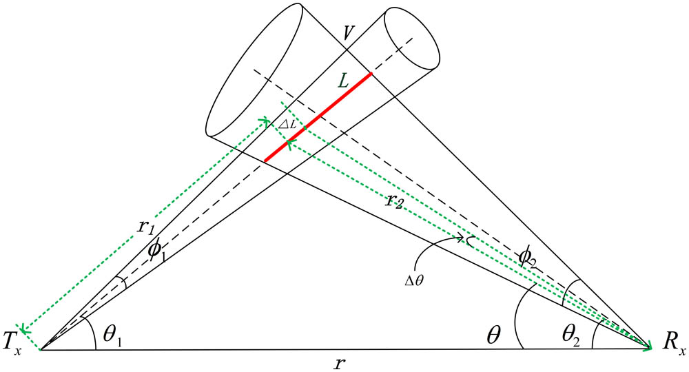
A typical single-scatter UV link is shown in Fig. 1. Parameters , , , , and are the communication baseline, Tx elevation angle, Rx elevation angle, Tx beam divergence, and Rx FOV angle, respectively. In single-scattering, only scattering photons in the common volume of Tx and Rx may arrive at the receiver. Distinct from the previous regular frustum approximation of in the prolate-spheroidal coordinate system[15], in this Letter we approximate as a line segment (red bold line in Fig. 1) under the narrow beam divergence assumption (). In other words, is assumed to be small. This approximation is proven effective by simulations and measurements. In this case, the infinitesimal scattering energy at the infinitesimal segment is where is the arriving energy at the starting point of the segment , and is the transmitted power. , and . Terms , , , , and are coefficients of extinction, absorption, scattering, Rayleigh scattering, and Mie scattering, respectively. Term is the scattering probability of light traveling through , since the probability distribution function of the scattering distance is [18], and we have Since is infinitesimal, , and we obtain Only a small portion of reaches the receiver, which is where is the area of receiving aperture, and is the scattering phase function[15]. It is noted that there is a term in Eq. (1) in the previous frustum approximation[15], where is the solid angle of the beam and is the differential volume. Since when is assumed to be small enough, we have . This term appears in Eq. (3) and thus Eq. (4), which is consistent with the previous model. According to the sine law, , , and . Substituting these expressions and Eq. (3) into Eq. (4), we obtain Consequently, the CPL is expressed as Equation (6) can be simplified further by using mean value theorem of integrals[19]. The key is to find a proper mean value . Through extensive comparisons between the parametric expression (PE) method and MCSs under typical geometrical configurations (, , , and ), we find the mean value is close to when and are large (approach 90°), and is close to when and are small (approach 0°); consequently, an empirical term is designed, which is a linear combination of and . Compared with the previous model where is fixed at the geometrical mean value [15], this empirical is proven to be a better fit by subsequent simulations and experiments. Consequently, Eq. (6) is reduced as The scattering phase function can be obtained from the Rayleigh scattering function and Mie scattering function .
In the deep-UV band, the model parameters , , and are usually set as 0.017, 0.72, and 0.5[10], leading to reduced . The expression is difficult to simplify, so we adopt the curve fitting method. A negative exponent function is found to be a good fit as , as shown in Fig. 2.
Substitute and into Eq. (7). We obtain the following PE where parameters , , , and are 0.0284, 0.089, 2.037, and . Equation (8) can be written as where A and C are functions of , , and .
Define . The computed by ray-tracing-based MCS developed in Ref. [11] and the PE in Eq. (8) under various and configurations are shown in Fig. 3. It can be seen that the CPLs of MCS and PE are close in most of the and region and . The CPL difference can be quantitatively compared in terms of the root-mean square error (RMSE) defined as , where is the number of data points. is 0.74 dB for Fig. 3.
Figure 3.Comparison of MCS and PE at different ( and ); , , , , and : (a) MCSs; (b) PE.
Table 1 shows the results at different communication distances (other parameters are the same as in Fig. 3). For comparison, the results from the previous CPL expression[15] are also listed. It can be seen that the error of the PE remains consistently small as the communication distance expands, and lower than 1 dB. This is a significant improvement compared with previous results[15], and also indicates that the PE model approximates the MCS model very well, but the computational complexity is 2 orders of magnitude lower than the MCS method. Table 2 further gives the results when , become larger, where and . The error increases only slightly with , .
In the previous paragraphs, we have shown that the proposed PE model approximates the MCS model very well. Next we compare it with our outdoor UV test-bed-based CPL measurements to show how accurate our model is. The experiments were conducted in a clear fine night to minimize the influence of background irradiation. A 36-chip LED array centered at 280 nm is employed as the source and its output optical power is 25 mW. The photodetector is a photomultiplier tube (PMT), Model Hamamatsu R7154. At the receiver, a photon counter was used to calculate the received optical power. The measured CPLs and their counterparts calculated by proposed PE are shown in Fig. 4. The RMSE between the PE method and measurements is about 2.44 dB, a reasonably small error which might be due to inaccurate atmospheric coefficients and system errors.
Figure 4.Comparison of CPLs by outdoor measurements and our proposed PE at different elevation angles; , , , , and .
The CPLs from the proposed PE method is also compared with the experimental CPL results reported[9], in Fig. 5. In most regions the calculated PE stays close to the measured value, and the RMSE is 4.26 dB for 81 data points (average measured CPL is 98.66 dB). It should be noted that the atmospheric parameters are difficult to obtain in CPL measurements[9], and the coefficients (, , and ) used in the PE method are obtained under typical “23-km-visible” conditions using the MODTRAN5 software package. Since the used atmospheric coefficients in PE may not be in perfect agreement with realistic ones, and there are unavoidable differences of other conditions between the calculation and measurement as well, the absolute RMSE is slightly larger in Fig. 5; however, the trends of both curves are similar, and the predicted average CPL () and measured average CPL () are on the same order of magnitude. Combining the results of Fig. 4, it is concluded that the proposed PE can well-estimate the actual CPL in most typical geometrical and system configurations, and is suitable for link analysis.
Figure 5.Comparison of CPLs by measurements[9] and our proposed PE at different elevation angles; , , , , : (a) front view of CPL surfaces; (b) side view of CPL surfaces.
The proposed CPL PE has been proven in the previous paragraphs to be a good alternative of MCSs in many cases, and a powerful tool for link analysis and performance estimation. We next discuss the intrinsic relationships between the CPL and geometrical parameters based on Eq. (8) to gain some insight into the link behavior. In the LOS case, the relationship between the CPL and communication range is generally classified as geometrical attenuation (GA) which follows the form and atmospheric attenuation (AA) which follows the form, where A is a constant, B is usually equal to 2, and C is 1. For the NLOS case, the concepts of GA and AA are assumed keeping effective. However, the coefficients A, B, and C do not follow the simple laws: (1) for AA, since the equivalent communication distance is relevant to geometrical configurations, the coefficient C of the exponential term is expressed as according to Eq. (8); (2) for GA, since the common volume redistributes the UV energy which can be viewed as the secondary source with beam divergence following the scattering phase function, the beam divergence does not affect the GA dramatically and can be made a linear approximation for the small case, which is very different from the LOS case. Additionally, when , , , and are fixed, the approximation of the common volume is proportional to the range , although the scattering energy emitted by each has an form attenuation at the receiving end, and an form (linear attenuation) is obtained by integrating through the entire segment .
In conclusion, we propose a PE for UV single-scattering CPL by joint analytical and empirical approaches. Extensive simulations show the proposed PE matches the existing MCS model very well, with a RMSE lower than 1 dB in most cases. It is also shown that the proposed PE produces path loss results consistent with outdoor experimental measurements based on our test-bed and reported measurements in the literature.