Xin Gao, Xinzhu Sang, Xunbo Yu, Wanlu Zhang, Binbin Yan, Chongxiu Yu. 360° light field 3D display system based on a triplet lenses array and holographic functional screen[J]. Chinese Optics Letters, 2017, 15(12): 121201
Copy Citation Text
A 360° light field 3D display system is presented, which consists of a liquid crystal display, a novel triplet lenses array, and a holographic functional screen (HFS). The mapping relationship among pixels, 3D objects, and viewing positions are investigated. The aberration analysis of the single lens is carried out both in the simulation and the experiment, which shows that it cannot provide an excellent 3D image to the viewers. In order to suppress the aberrations, “the primary aberration theory” and “the damped least-squares method” are used for optical analysis and lens design. A 3D image with aberration correction can be viewed around the proposed display system.
In the most glasses-free 3D displays, the 3D images can be viewed only from the normal direction. For example, the auto-stereoscopic display based on a liquid crystal display (LCD) and a lenticular sheet[1] can only provide limited views in a small viewing zone. Although the full-parallax 3D images can be viewed by the volumetric display, the occlusion effect is the existing problem[2,3]. The holographic display can regenerate the amplitude and phase of the recorded object. However, the large size, true color, and large viewing angle are difficult to be realized due to the limitation of the device[4–7]. In order to observe the 3D images in any position around the display area, a considerable amount of efforts have been dedicated to implement the 360° table display system. A 360° 3D display system based on multi-directional backlight was proposed[8]. However, the color saturation is limited due to the diffraction optical element. A 360° 3D display based on a multiplexed light field was proposed[9]. The crosstalk for the display is caused by the reflected light from adjacent auto-stereoscopic displays. In addition, it is adverse to communicating to each other for these observers around the pyramidal half-silvered mirrors. Many researchers pay much attention to the table 3D display system based on the projector. A multi-projection table 3D system was proposed[10,11]. Due to the use of a large number of projectors, the system is too expensive and complicated. In order to simplify the system, a high-speed projector, a spinning screen, and a rotating machine are employed to realize the 360° 3D display system[12–14]. Unfortunately, the number of colors or gray levels and the display size are limited by the high-speed projector and spinning screen. A hybrid system, which combines the multiple projector system and the high-speed projector system, is demonstrated[15]. Even so, the hybrid system is still unstable and uneconomic. The integral imaging system has generated great interest over the past few decades given its ability to produce full-parallax, full-color, and real-time 3D images. However, one of the main limitations of integral imaging is the narrow viewing angle, so that it is difficult appling in the 360° table display system. Jang proposed a new method for enhancing the viewing angle[16]. A high refractive index medium is used to increase the NA of the optical system, thus improving the viewing angle. Kim et al. proposed to use a flexible screen and a curved lens array to achieve the large viewing angle[17]. Park et al. proposed a multi-viewer tracking integral imaging system[18]. Unfortunately, these methods for enlarging the viewing angle degrade the quality of 3D images. In order to solve these problems, a 360° light field 3D display system based on a novel triplet lenses array and a holographic functional screen (HFS) is presented. In the demonstrated system, the LCD is used to display the synthetic images. The novel triplet lenses array is designed according to the characteristic of a ring-shaped viewing area and used to ensure the large viewing angle and suppress the aberrations of the 3D images. A realistic, improved image quality, and distortionless 3D image can be viewed.
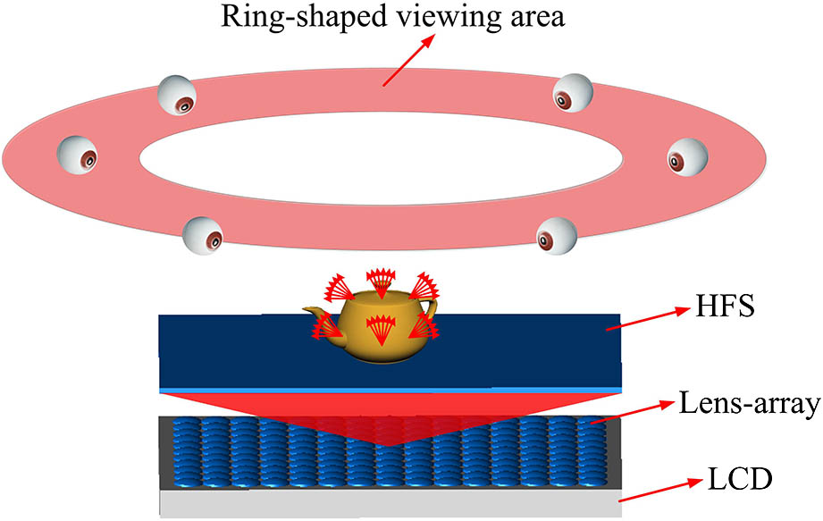
Figure 1 shows the basic structure of the proposed 3D display system, which is mainly comprised of a flat panel display device, an HFS, and a lens-array. The HFS can diffuse and limit the incident light in a solid diffusing angle. The operating principle and the fabrication method were introduced in Refs. [19–21]. The object is captured by a set of virtual cameras around 360°, thus creating a parallax image array. The display panel is divided into numerous sub-display regions for the corresponding parallax element image. Each lens and the corresponding parallax element image make up a so-called projector. All of the parallax element images are projected onto the HFS. Then, the regenerated 3D images can be viewed in the ring-shaped viewing area.
Figure 1.Schematic diagram of 360° light field 3D display.
As illustrated in Fig. 2, the viewing area of the proposed display system is ring-shaped. Due to the fact that the system is rotationally symmetric, only the radial viewing positions are analyzed without loss of generality. Different pixel generate corresponding directional light rays to viewing positions via corresponding lenses in the lens array. and are the radial distance of viewing positions and . and are the horizontal distance between the optical axis of the lens unit and point O. and are the viewing angles of viewing positions and . is the distance from the lens array to the HFS, and is the distance between the lens array and the LCD. represents the height of the viewing area, and represents the distance of the adjacent lenses. To display a spatial point O of the real 3D scene, the specific light rays emitting from point O are reconstructed. Inorder to implement the image synthesis algorithm, the mapping relationship among the pixels, the reconstructed 3D object, and the viewing positions are demonstrated. Using viewing positions and as an example, the light from or is projected to the scene of point O first. Then, it is projected to the lens array to find the corresponding projected lens. Finally, the light is extended to find the corresponding pixel or on the LCD screen. The geometrical relationship can be expressed as
Sign up for Chinese Optics Letters TOC. Get the latest issue of Chinese Optics Letters delivered right to you!Sign up now
Figure 2.Reconstruction of spatial points and mapping relationship.
In Eq. (1), is the focal length, and or is the distance from pixel or to the corresponding optical axis of the lens unit. According to the geometrical relationship and optical principles, and can be calculated as follows:
For two nearby viewing positions, such as and , the light rays reconstructing virtual point O come from pixels and via two adjacent lenses. In fact, there is another virtual point that can be viewed at a certain viewing position between and . The virtual point is very close to the virtual point O, and it is reconstructed by other pixels between pixels and . Based on the above analysis, the smooth motion parallax and stereo parallax can be achieved by this regenerating light field display approach.
In the proposed display system, the HFS is placed on the image plane of the lens array. It diffuses the incident light rays in a certain angle to ensure that observers can watch the consecutive images. The diffusing angle is related to the specific parameters of the display system. As shown in Fig. 3, and are two adjacent lenses, is the aperture of the lens unit, and is the diffusing angle. If the diffusing angle is zero, the instructed image can be observed only in areas A and B, but not in the area marked with a red line. In order to realize the consecutive images, the light rays and should be diffused to . Thus, the diffusing angle can be calculated by the following equation:
Figure 3.Relationship between the diffusing angle of the HFS and lens parameters.
Based on the above analysis, the lens array is the key component to project the synthesis images to the HFS. Thus, the imaging quality of the lens is the important factor for reconstructing an excellent 3D light field. In the following discussion, the size of the lens array is 23.6 inch (), the aperture of the lens unit is , the distance of the adjacent lens unit is , the image distance is , the height of viewing area is , and the radius of the ring-shaped viewing area is from to . According to Eqs. (1)–(3), we can obtain that the range of the viewing angle is from to , and the focal length is . Under this situation, if the lens unit in the lens array is a single lens, the imaging quality will be extremely poor.
The spot diagram of the single lens and corresponding root-mean-square (RMS) radius are shown in Fig. 4.
Figure 4.Spot diagram of a single lens with (a) 0° viewing angle, (b) 21° viewing angle, and (c) 30° viewing angle.
Figures 4(a), 4(b), and 4(c) illustrate the spot diagram of different viewing angles. If a 4k LCD with the size of 23.6 inch () is used to display synthesis images, the pixel size is about . On the basis of the system magnification and Rayleigh criterion, the RMS radius of the spot projected on the HFS must be less than 2470 μm. However, the RMS radius of the single lens is far greater than this value shown in Figure 4. A 360° light field 3D display system with a single lens array is assembled in order to demonstrate that aberrations have an effect on the performance of the display system. The specific parameters of the display system are listed in Table 1. The diffusing angle of the HFS could be calculated by Eq. (4).
Figures 5(a) and 5(b) are photos of the reconstructed teapot taken from two directions. The aberrations seriously affect the image quality of the reconstructed 3D images. In order to resolve this problem, the primary aberration theory is used to calculate the initiating structure. The formula can be obtained as follows: where represent five different types of monochromatic aberrations, respectively, and are two types of chromatic aberrations. is the Lagrange invariant, and is the diopter. and represent the incident height of the first and second paraxial rays. and are the refractive index and Abbe constant. As shown in Eqs. (5) and (6), there are seven primary aberrations to be calculated. It is impossible to obtain a satisfactory result with a single lens since there are only two variables for the optimization. Thus, the compound lens consisting of three lenses is used to eliminate seven primary aberrations. After primary aberrations are eliminated, the initiating structure can be obtained, and the parameters are listed in Table 2. However, it is difficult to achieve a high-quality image performance due to the existence of a large number of high-order aberrations. The method of damped least-squares is adopted to balance the primary aberrations and the high-order aberrations. The optimized lens is marked by Cooke-1, and the related parameters are listed in Table 3. Figure 6(a) illustrates the structure of Cooke-1, and Figs. 6(b), 6(c), and 6(d) are corresponding spot diagrams.
As shown in Fig. 6(a), Cooke-1 consists of two positive power lenses and a negative power lens. It suppresses the aberrations and reduces the RMS radius, as shown in Figs. 6(b), 6(c), and 6(d). In general, the image quality of the mid-viewing angle is better than that of the marginal viewing angle, such as Figs. 6(b) and 6(d). However, in the proposed display system, it is natural for observers to watch the 3D images in the marginal ring-shaped area, instead of from the top of the system. As mentioned previously, the ring-shaped viewing area is from 21° to 30°. Thus, in order to reconstruct a better 3D image, we should focus on optimizing the image quality of these viewing angles. The optimizing strategy is adjusted to increase the weight of these viewing angles and reduce that of other viewing angles. After adjusting the weight multiple times, a satisfactory structure is obtained. The related parameters are listed in Table 4.
Figure 6.Spot diagram of Cooke-1. (a) The Cooke-1 model, (b) 0° viewing angle, (c) 21° viewing angle, and (d) 30° viewing angle.
As shown in Table 4, each lens of the novel triplet lenses is the positive power, and they are unsymmetrical due to the fact that the marginal viewing area is the region of interest. The corresponding spot diagram is shown in Fig. 7. Compared with Cooke-1, the RMS radius of the viewing angle from 21° to 30° is reduced. Note that the RMS radius of the mid-viewing angle of the novel triplet lenses is larger than that of Cooke-1, as shown in Fig. 7(a), as these two structures use different weight values for the optimization of the optical design. To assess the image quality more comprehensively, the modulation transfer function (MTF) of different viewing angles and distortions should be considered.
Figure 7.(Color online) Spot diagram of the novel triplet lenses with (a) 0° viewing angle, (b) 21° viewing angle, (c) 27° viewing angle, and (d) 30° viewing angle.
According Fig. 8(a), the MTF values from 0° to 10° are smaller than 0.2, which means that the 3D quality of the mid-viewing area is deteriorative. But, the MTF values of the ring-shaped viewing area marked by blue circles are larger than 0.6, which are obviously higher than that of the single lens array. The maximum distortion is 2.42%, and it can be ignored for human vision, as shown in Fig. 8(b). An improved image quality, distortionless, and 360° display performance can be expected.
Figure 8.(Color online) (a) Tangential “MTF curve.” (b) Grid distortion on the image plane.
A table floating light field 3D display system with a 360° view has been developed. The viewing angle of the ring-shaped area is from 21° to 30°. As shown in Fig. 9(a), a flat panel display device with the size of 23.6 inch and the resolution of is used to load the synthetic images [Fig. 9(b)]. A novel lens array consisting of a triplet lenses unit is placed in front of the display device. The aperture and the focal length of each lens unit are 10 and 10.39 mm, respectively. An HFS is placed on the image plane of the lens array, and the image distance is 200 mm. The 8100 virtual cameras are arranged as a 2D array to capture a teapot from different perspective directions.
Figure 9.(a) System structure and (b) the synthetic image.
Figures 10(a)–10(h) are captured in the ring-shaped viewing area with the viewing angle (Fig. 2). Fig. 10(i) is the original model. Compared with the reconstructed images shown in Fig. 6, the image quality is significantly improved in the proposed system. It is worth noting that the images will be darker with the increasing due to the vignetting effect.
Figure 10.360° 3D images. (a)–(h) are captured from different positions in the ring-shaped viewing area with the viewing angle . (i) The original model.
In conclusion, the 360° 3D display with the correct occlusion effect is presented. The mapping relationship is analyzed to create the element images on the basis of the position of observers. Due to the requirement of large angle, a single-lens array is unable to achieve the satisfactory image quality. In order to improve the quality of 3D images and ensure the large viewing angle, Cooke-1 is designed to suppress aberrations. According to the characteristics of the viewing area, the novel triplet lenses are optimized by adjusting the weight of the viewing angle. The experiment verifies that an excellent table 3D display system can be achieved.
Xin Gao, Xinzhu Sang, Xunbo Yu, Wanlu Zhang, Binbin Yan, Chongxiu Yu. 360° light field 3D display system based on a triplet lenses array and holographic functional screen[J]. Chinese Optics Letters, 2017, 15(12): 121201