Álvaro Morales, Idelfonso Tafur Monroy, Fredrik Nordwall, Tommi Sørensen, "50 GHz optical true time delay beamforming in hybrid optical/mm-wave access networks with multi-core optical fiber distribution," Chin. Opt. Lett. 16, 040603 (2018)
Copy Citation Text
We propose and experimentally validate an optical true time delay beamforming scheme with straightforward integration into hybrid optical/millimeter (mm)-wave access networks. In the proposed approach, the most complex functions, including the beamforming network, are implemented in a central office, reducing the complexity and cost of remote antenna units. Different cores in a multi-core fiber are used to distribute the modulated signals to high-speed photodetectors acting as heterodyne mixers. The mm-wave carrier frequency is fixed to 50 GHz (V-Band), thereby imposing a progressive delay between antenna elements of a few picoseconds. That true time delay is achieved with an accuracy lower than 1 ps and low phase noise.
Although fiber optic technology is the preferred option to be used in the last mile segment, capital costs and environmental issues may prevent fiber-to-the-x (FTTx) networks to be deployed in several scenarios[1]. Moreover, as emerging multimedia applications continue evolving, new requirements in terms of bandwidth demands and mobility have the means to revise new access network architectures[2]. Millimeter (mm) -wave links (30–300 GHz) can be used as an alternative technology to extend the reach of optical fiber architectures coping with high bandwidth demands. The coexistence with already deployed optical distribution networks is assured, since many configurations of mm-wave transmissions for front and backhaul networks based on optical fiber distribution are being reported[3,4].
The main challenge of operating at the mm-wave range is the high free-space path loss and atmospheric absorption, causing difficulties in implementing long-distance links[5,6]. The best solution is the use of high gain directive antennas, which focus the radiated energy in a narrow beam, overcoming the power limitations. The small size of radiating elements at the mm-wave range allows for creating large antenna arrays with beamforming capabilities, offering new opportunities in terms of network reconfigurability and ubiquitous access[7].
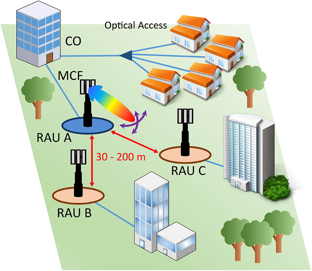
Figure 1 shows the described scenario. A wireless link is converged onto a fiber-optic-based access network to provide broadband access to end users who demand bandwidth-intensive applications, as it may be the case of offices, hotels, airports, or conference centers. The radio access unit (RAU) is responsible for optical to mm-wave conversion, centralizing the most complex functions (e.g., data modulation, wireless channel selection, and beamformer network) within the central office (CO). In this radio-over-fiber (RoF) approach, data is transmitted as a baseband signal together with a tone separating the desired wireless carrier. The radio carrier is generated on a photodiode by optical heterodyning[8]. A multi-core fiber (MCF) is used to feed the array elements and transmits data back from the RAU. MCF technology has been declared as an effective method to increase the flexibility and capacity in access networks by transmitting independent space-multiplexed channels[9]. In this case, it is used to distribute the signals to remote antenna arrays, keeping the progressive time delay between cores. The MCF allows shifting of the beamforming functionality to the CO while the data is still transmitted over a single fiber. This change implies a reduction in the deployment cost of the RAUs. The beam steering capabilities allow switching between different antenna stations or even providing broadband access to moving targets[10]. The distance between RAUs for this frequency range is typically in the range from several tens of meters up to 200 m[2,11]. It depends on the power budget and emerging recommendations of standardization bodies.
Sign up for Chinese Optics Letters TOC. Get the latest issue of Chinese Optics Letters delivered right to you!Sign up now
Figure 1.Hybrid optical/mm-wave access network with beamforming capabilities. CO, central office; MCF, multi-core fiber; RAU, radio access unit.
In this Letter, a hybrid optical/mm-wave access network with optical true time beamforming capabilities and MCF distribution is presented and experimentally validated. Such an approach is proposed to enhance the reach of optical networks by incorporating the advantages of wireless links, such as mobility and ubiquitous access, together with beam steering capabilities. This work is significant because of two key ideas. Firstly, the system complexity is moved away from the remote antenna units, centralizing the beamforming network into the CO and transmitting the time delayed signals through a MCF. Secondly, the carrier frequency is raised up to the V-Band (50 GHz). As a consequence, a progressive signal delay in the order of a picosecond is needed between antenna elements. That time resolution is achieved with an accuracy lower than 1 ps and low phase noise.
Several techniques have been used over the years for beam steering at the mm-wave range[5,12]. The small size of antenna elements at this frequency range and the benefits offered by multiple antenna systems, including diversity, multiplexing, or beamforming, makes a phased array antenna (PAA) the main candidate to be used in the base stations. Furthermore, the optical true time delay (OTTD) assures wide operation bandwidth, low loss, immunity to electromagnetic interference, small size, and easy integration into deployed optical networks[13–15]. The operating principle of OTTD beamforming for a linear PAA is shown in Fig. 2. The modulated optical signal is split into the different branches that will feed the array elements. After that, each signal is delayed with a progressive delay and transmitted through a single core of an MCF to reach the photodiode array, which is used to convert the optical signal into the electrical domain by optical heterodyning. The relative delay is kept in the radio frequency domain[13].
Figure 2.Principle of optical true time delay beamforming in a linear phased antenna array.
The wave front is formed in the far-field pointing to the direction given by where is the direction angle, and represent, respectively, the time and phase difference between consecutive branches, is the distance between adjacent antennas, represents the light velocity in vacuum, and denotes the wavelength. There are two parameters that can be modified to change the beam pointing. First, the distance between antennas, which, in general, will be fixed to half of the operating wavelength in order to avoid grating lobes[16], leads to the expression where is the carrier frequency. The other parameter is the progressive delay between antenna elements. It can be proved by Eq. (2) that this delay must be in the range of , meaning that the time resolution increases with the carrier frequency. The time delay can be translated into phase difference by which will be in the range of []. In other words, as the carrier frequency is increased, the time delay needs to achieve a phase difference between [], which is shorter. As an example, for a carrier frequency of 50 GHz, we need to provide a progressive delay between adjacent elements in the range of .
Sign up for Chinese Optics Letters TOC. Get the latest issue of Chinese Optics Letters delivered right to you!Sign up now
The experimental setup is shown in Fig. 3. The first block represents the CO, where three functionalities are implemented: wireless carrier selection, data modulation, and beamforming network. The optical carrier suppression (OCS) technique is used to generate two correlated optical lines, reducing the phase noise[1]. A Mach–Zehnder modulator (MZM), which has been biased at the point, is fed by a free-running external cavity laser at and an optical power of 13.0 dBm (EMCORE TTX1994). The carrier frequency can be selected at this point by driving the radio frequency port by a sinusoidal tone with a frequency of . In this case, a vector signal enerator (VSG) provides a signal of 25 GHz and a power of 5.4 dBm. As a consequence, two spectral lines spaced at 50 GHz () are generated at the optical output. Afterwards, the signal is boosted by an erbium-doped fiber amplifier (EDFA) before the following step. A second MZM is used to modulate with a 5 Gb/s ()-bit-long pseudorandom bit sequence (PRBS15) non-return-to-zero (NRZ) signal provided by an arbitrary waveform generator (AWG) and a driving amplifier of 17 dB. In the last stage, the optical signal is powered up (12.7 dBm) and split into the two branches that will feed the antenna array. The relative delay between them is manually controlled by two reconfigurable optical time delay lines (OTDL) with 0.033 ps resolution. They are both used to compensate length mismatches between the two paths and provide the desired delay configuration [Fig. 3(a)]. For experimental demonstration, a beamformer network is implemented. However, the results can be generalized for a larger number of antenna elements. The OTDL outputs are launched into two different cores of a 2 km MCF, representing the optical link between the CO and RAU. The MCF used in this experiment is a seven-core fiber manufactured by OFS Labs[17]. The cores are arranged in a regular hexagonal array by a central core with a core pitch of 38 μm between all of them. The fiber is connected to two fan-in/fan-out modules by fusion splicing before being implemented in the system. The measured insertion loss and cross-talk are shown in Table 1. Cores 0 and 4 are chosen for this experiment because they have lower insertion loss. In a real scenario, the number of array elements would be limited by the number of cores. However, MCFs with many cores have already been developed (several tens). Moreover, different MCFs can be used to provide the delay configuration to different subsections of a larger array. Afterwards, the RAU A in Fig. 1, working as a transmitter, is emulated. The radio frequency signals are generated on two 70 GHz bandwidth photodiodes (Finisar XPDV3120) acting as heterodyne mixers, keeping the relative delay from the optical domain [Fig. 3(b)]. The optical power before both photodiodes is fixed to 2.2 dBm by two variable attenuators. This is the maximum power achieved with the described optical distribution network, which assures the operation below the saturation point of the photodiodes (3 dBm). It can be seen in the optical spectrum in Fig. 3 that the optical carrier is not completely suppressed, resulting in additional undesirable signals after photonic up-conversion. However, these photomixing products will be laid far enough from the frequency band of interest to be filtered out by the mm-wave components. Finally, a 70 GHz scope (Tektronik DPO70000SX Series) is used to capture the output signals for off-line processing [Fig. 3(c)].
Core
0
1
2
3
4
5
6
Insertion loss (dB)
3.1
5.3
4.0
3.9
3.8
4.7
4.0
Cross-talk (dB)
−32.0
−34.7
−36.2
−37.6
−34.8
−32.2
−35.0
Table 1. Measured Insertion Loss and Cross-talk at 1550 nm for the Seven-core Fiber
The results presented in the following paragraphs validate the feasibility of the architecture with beam steering capabilities proposed in this work. Four configurations of the beamforming network are studied, corresponding with a delay difference of or a phase difference of . Figure 4 shows the captured signals during a short time interval, so it can be demonstrated by visual inspection that the desired delays can be achieved.
Figure 4.Experimental demonstration of proposed OTTD beamforming scheme in four scenarios: , , , and .
The captured data is resampled by a factor of 5 to measure the delay difference between both channels. The obtained results are shown in Table 2. The average delays are very close to the ideal delays set by the beamforming network with a maximum error of 0.3 ps in the case of . This time error can be translated into angular error in the beam pointing by using Eq. 2, obtaining a maximum error of around 2°. The data is also split into smaller ranges to compute the stability and phase noise of the signals. It is depicted in Fig. 5. The standard deviation of the delay is computed to be around 0.1 ps in all cases (0.7°) with a maximum deviation of 0.5 ps (2.87°). The beamwidth of antenna arrays operating at these frequency ranges can be made wide enough to afford these errors.
Beamforming Network Delay (ps)
Average Delay (ps)
Absolute Error
Standard Deviation
Maximum Deviation
−5
−5.18
0.18 ps/1.03°
0.11 ps/0.63°
0.48 ps/2.75°
0
0.10
0.10 ps/0.57°
0.14 ps/0.80°
0.40 ps/2.29°
5
4.66
0.34 ps/1.95°
0.12 ps/0.69°
0.46 ps/2.64°
10
10.20
0.20 ps/1.15°
0.13 ps/0.74°
0.50 ps/2.87°
Table 2. Measured Results of Delay Between Two Channels
Finally, the measured signals are digitally filtered and demodulated through envelope detection to assure that the transmitted information has not been corrupted. Figure 6 shows the eye diagrams with extinction ratios of 16.2 and 18.1 dB, respectively.
In this Letter, we presented a scheme to integrate a mm-wave wireless link with beamforming capabilities into an optical access network. The signal feeding an array element is delayed in the optical domain and transmitted through a core of an MCF until reaching a high bandwidth photodiode. The optical to electrical conversion is performed by optical heterodyining, keeping the relative delay in the radio frequency domain. Experimental results prove the feasibility of the proposed OTTD technique selecting a carrier frequency of 50 GHz. Sub-picosecond accuracy is achieved for the relative delay between elements with a maximum average error of 0.3 ps (2°) and good stability. This solution assures full convergence with the optical fiber infrastructure. Our results serve as engineering guidelines for the implementation of mm-wave wireless links in the last mile segment, centralizing the beamforming control by using an MCF for signal distribution.