• Laser & Optoelectronics Progress
  • Vol. 58, Issue 9, 0913001 (2021)
Junping Gao1、2, Mengmeng Zhao1、2, Jia Lu1、2、*, Jianfei Liu1、2, and Jingfei He1、2
Author Affiliations
  • 1School of Electronics and Information Engineering, Hebei University of Technology, Tianjin 300401, China
  • 2Tianjin Key Laboratory of Electronic Materials & Devices, Tianjin 300401, China
  • show less
    DOI: 10.3788/LOP202158.0913001 Cite this Article Set citation alerts
    Junping Gao, Mengmeng Zhao, Jia Lu, Jianfei Liu, Jingfei He. Wide Optical Frequency Comb System Based on Single Intensity Modulator[J]. Laser & Optoelectronics Progress, 2021, 58(9): 0913001 Copy Citation Text show less
    Principle diagram of system and spectra of optical frequency comb. (a)Principle diagram;(b1)input and (b2) output carrier spectra of MZM
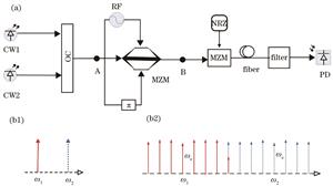
    Fig. 1. Principle diagram of system and spectra of optical frequency comb. (a)Principle diagram;(b1)input and (b2) output carrier spectra of MZM
    Bessel function curves under different modulation coefficients
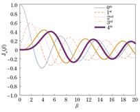
    Fig. 2. Bessel function curves under different modulation coefficients
    Standard deviations between the sidebands of different orders under different modulation coefficients
    Fig. 3. Standard deviations between the sidebands of different orders under different modulation coefficients
    Bessel function curve of n-order sideband
    Fig. 4. Bessel function curve of n-order sideband
    Output optical frequency comb spectrum of modulator
    Fig. 5. Output optical frequency comb spectrum of modulator
    Bit error rate curves demodulated under different order sidebands
    Fig. 6. Bit error rate curves demodulated under different order sidebands
    Eye diagrams of different order components of continuous wave and eye diagrams obtained by demodulation at receiving terminal after transmission through optical fiber. (a) Positive third-order component of CW1; (b) negative third-order component of CW2; (c) synthetic sideband component; (d) positive third-order component of CW1 after transmission through optical fiber; (e) negative third-order component of CW2 after transmission through optical fiber; (f) synthetic sideband component after transmission through optical fiber
    Fig. 7. Eye diagrams of different order components of continuous wave and eye diagrams obtained by demodulation at receiving terminal after transmission through optical fiber. (a) Positive third-order component of CW1; (b) negative third-order component of CW2; (c) synthetic sideband component; (d) positive third-order component of CW1 after transmission through optical fiber; (e) negative third-order component of CW2 after transmission through optical fiber; (f) synthetic sideband component after transmission through optical fiber
    Relationship between modulation voltage and flatness
    Fig. 8. Relationship between modulation voltage and flatness
    2.82.93.03.13.23.3
    0th-0.1850-0.2243-0.2601-0.2921-0.3202-0.3443
    1st0.40970.37540.33910.30090.26130.2207
    2nd0.47770.48320.48610.48620.48350.4780
    3rd0.27270.29110.30910.32640.34310.3588
    4th0.10670.11900.13200.14560.15970.1743
    Table 1. Bessel functional values corresponding to 0th?4th order sidebands under different modulation coefficients
    Junping Gao, Mengmeng Zhao, Jia Lu, Jianfei Liu, Jingfei He. Wide Optical Frequency Comb System Based on Single Intensity Modulator[J]. Laser & Optoelectronics Progress, 2021, 58(9): 0913001
    Download Citation