• Laser & Optoelectronics Progress
  • Vol. 56, Issue 10, 101403 (2019)
Yingyi Ma, Yude Liu*, Wentian Shi, Peng Wang, Bin Qi, Jin Yang, and Dong Han
Author Affiliations
  • School of Materials Science and Mechanical Engineering, Beijing Technology and Business University, Beijing 100048, China
  • show less
    DOI: 10.3788/LOP56.101403 Cite this Article Set citation alerts
    Yingyi Ma, Yude Liu, Wentian Shi, Peng Wang, Bin Qi, Jin Yang, Dong Han. Effect of Scanning Speed on Forming Defects and Properties of Selective Laser Melted 316L Stainless Steel Powder[J]. Laser & Optoelectronics Progress, 2019, 56(10): 101403 Copy Citation Text show less
    316L stainless steel powder. (a) Morphology; (b) particle size distribution
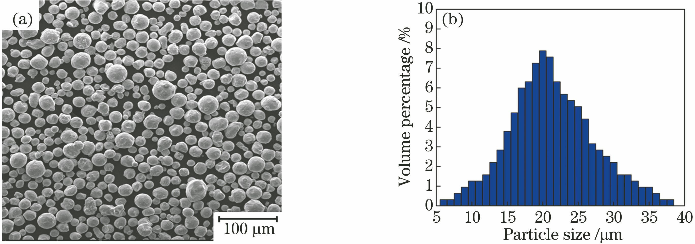
    Fig. 1. 316L stainless steel powder. (a) Morphology; (b) particle size distribution
    Formation process of SLM block
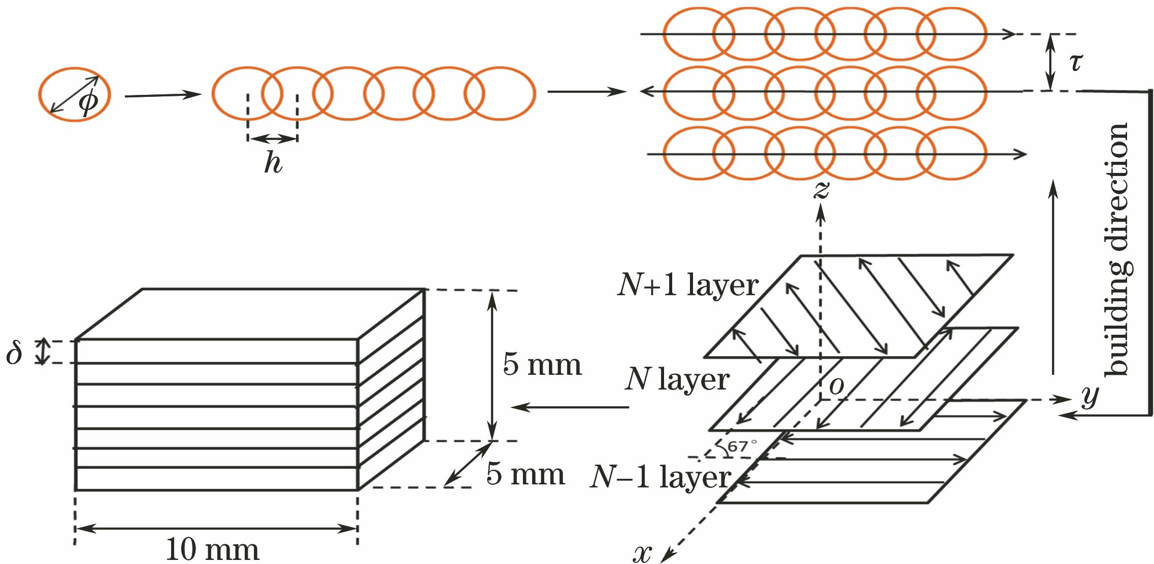
    Fig. 2. Formation process of SLM block
    Tensile specimen. (a) Geometric size; (b) finished product
    Fig. 3. Tensile specimen. (a) Geometric size; (b) finished product
    Surface morphologies of samples under different scanning speeds and hatch spaces. (a) 500 mm·s-1; (b) 750 mm·s-1; (c) 1000 mm·s-1; (d) 1250 mm·s-1
    Fig. 4. Surface morphologies of samples under different scanning speeds and hatch spaces. (a) 500 mm·s-1; (b) 750 mm·s-1; (c) 1000 mm·s-1; (d) 1250 mm·s-1
    Densities of samples under different scanning speeds. (a) 500 mm·s-1; (b) 750 mm·s-1; (c) 1000 mm·s-1; (d) 1250 mm·s-1
    Fig. 5. Densities of samples under different scanning speeds. (a) 500 mm·s-1; (b) 750 mm·s-1; (c) 1000 mm·s-1; (d) 1250 mm·s-1
    Cross-sectional morphologies of samples under different scanning speeds when hatch space is 110 μm. (a) 500 mm·s-1; (b) 750 mm·s-1 ; (c) 1000 mm·s-1 ; (d) 1250 mm·s-1
    Fig. 6. Cross-sectional morphologies of samples under different scanning speeds when hatch space is 110 μm. (a) 500 mm·s-1; (b) 750 mm·s-1 ; (c) 1000 mm·s-1 ; (d) 1250 mm·s-1
    Sample forming defects. (a) Spatter phenomenon; (b) spatter defect; (c) big blow hole; (d) unmelted defect; (e) balling phenomenon; (f) balling defect; (g) small blow hole; (h) crack
    Fig. 7. Sample forming defects. (a) Spatter phenomenon; (b) spatter defect; (c) big blow hole; (d) unmelted defect; (e) balling phenomenon; (f) balling defect; (g) small blow hole; (h) crack
    Formation process of spatter and pore
    Fig. 8. Formation process of spatter and pore
    Formation process of balling and pore
    Fig. 9. Formation process of balling and pore
    Formation process of blow hole. (a) Low speed big blow hole; (b) high speed small blow hole
    Fig. 10. Formation process of blow hole. (a) Low speed big blow hole; (b) high speed small blow hole
    Microstructures of samples under different scanning speeds. (a) 750 mm·s-1; (b) 500 mm·s-1; (c) 750 mm·s-1
    Fig. 11. Microstructures of samples under different scanning speeds. (a) 750 mm·s-1; (b) 500 mm·s-1; (c) 750 mm·s-1
    Tensile properties of samples under different hatch spaces when scanning speed is 750 mm·s-1
    Fig. 12. Tensile properties of samples under different hatch spaces when scanning speed is 750 mm·s-1
    CrNiMoMnSiPCSFe
    16-1810-142-3≤2≤1≤0.045≤0.03≤0.03Bal.
    Table 1. Chemical compositions of 316L stainless steel powder (mass fraction, %)
    Scanning speed /(mm·s-1)Defectratio /%
    SpatterAir bladderCrackUnmelted defectBalling
    5000.10690.09720.00970.01220.0170
    7500.01750.01050.00140.00300.0026
    10000.01140.01300.00820.07340.0571
    12500.01710.03290.00710.71450.6573
    Table 2. Defect ratios under different scanning speeds
    Yingyi Ma, Yude Liu, Wentian Shi, Peng Wang, Bin Qi, Jin Yang, Dong Han. Effect of Scanning Speed on Forming Defects and Properties of Selective Laser Melted 316L Stainless Steel Powder[J]. Laser & Optoelectronics Progress, 2019, 56(10): 101403
    Download Citation