Abstract
The far-field imaging properties of a high index microsphere lens spatially separated from the object are experimentally studied. Our experimental results show that, for a Blu-ray disk whose spacing is 300 nm, the high index microsphere lens also can discern the patterns of the object sample when the distance between the lens and the object is up to 5.4 μm. When the distance is increased from 0 to 5.4 μm, for the microsphere lens with a diameter of 24 μm, the lateral magnification increases from 3.5× to 5.5×, while the field of view decreases from 5.1 to 3.0 μm. By varying the distance between the lens and the object, the optical image can be optimized.We also indicate that the far-field imaging capability of a high index microsphere lens is dependent on the electromagnetic field intensity profile of the photonic nanojet under different positions of the microsphere lens.1. INTRODUCTION
Many novel optical properties of a microsphere lens such as photonic nanojets [1–3], whisper gallery modes [4], Poynting field [5,6], light compression [7], and super-resolution imaging [8–17] have been observed. Microsphere-assisted microscopy is a simple and effective approach to obtain super-resolution imaging. This technique has the potential to apply label-free [11] and fluorescent biomedical imaging [12] in real time under white light illumination. Schwartz et al. have successfully obtained single molecule imaging by using a high refractive index colloid with a diameter of 2 μm [13]. Lee et al. have observed near-field focusing and magnification through a microsphere lens and indicated that there is a connection between the super-resolution capability of the lens and the super-strength focus in the near field [14]. Wang et al. have experimentally demonstrated that a microsphere with a low refractive index in the diameter range of 2–9 μm can be used to collect and magnify subdiffraction limited features, and the lateral resolution is up to 50 nm [15]. The microscale spherical lens can capture the subdiffraction limited details of an object, magnify it, and form a virtual image underneath the surface of the microsphere lens by converting the high spatial frequency components of the evanescent field into a propagating wave. Recent experiments demonstrate that, when the low refractive index microsphere lens is semi-immersed in a liquid droplet, the super-resolution capability can be reinforced, thus forming a sharper contrast image [16]. The fully immersed microsphere lens with high refractive index also can discern the fine structures with a minimum size of , and the field of view (FOV) is large due to the diameter of the imaging microsphere being larger than 100 μm [17]. Studies also show that, when the lens and the object are not closely contacted, the lens with low refractive index also can magnify the stripe patterns of the object samples [18,19]. Moreover, a high refractive index microsphere presents many advantages in prefabrication and location movement because it can be embedded in transparent solidified films used as cover slips to observe the samples [10]. Darafsheh et al. have observed the radiation-induced glioblastoma cells using a high index microsphere embedded in elastomers [7]. Considering the application superiority of a high index microsphere, although the far-field properties of low-index lens are well studied, the imaging properties of high-index lenses in a far-field need to be further revealed. In this work, we use a barium titanate glass (BTG) microsphere with a high refractive index () to image the Blu-ray disk (BD) sample. Our experimental results show that, for our object sample with a spacing of 300 nm, the high-index lens performs novel far-field properties. When the distance between the microsphere and the sample is increased from 0 to 5.4 μm, the lateral magnification increases from to , and the FOV decreases from 5.1 to 3.0 μm. These properties are different from the properties of a low index lens. Our results provide an optimization method to improve the magnification and eliminate the dark area in the center of the image by keeping the object sample at an appropriate distance away from the high refractive index microsphere lens.
2. EXPERIMENTAL ARRANGEMENT
Figure 1(a) shows that a ZEISS microscope equipped with microscope objectives and a CCD camera are used to observe the object. The microscope works under white-light illumination with a peak wavelength of 540 nm and reflective mode. Our object is a commercial BD with its protection layer peeled off before use. The BD sample consists of 200 nm stripes separated by 100 nm grooves, as shown in Fig. 1(b). The fine structures of the BD sample cannot be resolved by a conventional optical microscopy. A layer of SU-8 resist was spin coated on the top of the disk. When an SU-8 layer is coated on top of the objects, the Rayleigh resolution limit for line objects is 225 nm (): here, , (the refractive index of SU-8), and (for a microscope objective) [20]. Therefore, our object is larger than the resolution limit. The SU-8 layer was then exposed, developed, and crossed-linked. We can control the thickness of the SU-8 layer by using a different type of SU-8 resist and different spin speed. Then, the high refractive index BTG microsphere lenses were spread on the top of the SU-8 coated disk. In order to obtain a high-resolution image, a drop of ethanol was placed on the microsphere and the microsphere fully immersed in ethanol. Finally, the magnified virtual image underneath the surface of the microsphere was captured through the microscope. We chose the microsphere with a diameter of 24 μm to image the BD sample using the () microscope objective. The thickness of the SU-8 layer was measured by a step profiler (AMBios Technology, XP-1). The distance between the object and the microsphere is 0, 0.6, 1.4, 2.2, 3.5, and 5.4 μm for our samples, respectively.
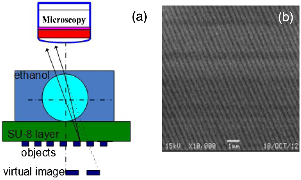
Figure 1.(a) Schematic of the experimental setup. (b) SEM image of a blank BD studied in this paper.
3. RESULTS AND DISCUSSION
Figure 2 shows the observed optical images of the BD through the microscope assisted by the microscale lenses. When the microsphere lenses were fully immersed in the ethanol, the stripe patterns of the disk would appear inside the microsphere. The microscale lens produced an enlarged image of the object, which can be observed by a conventional optical microscopy. For all the samples, the optical images are underneath the surface plane of the microsphere, thus indicating that all the images are virtual images. We investigate the lateral magnification and FOV properties of the high index microsphere lens as a function of . As Fig. 3(a) shows, the magnification depends on the thickness of the SU-8 layer; it increases as the distance increases. In our studied range, the magnification changes from to when increases from 0 to 5.4 μm, while the FOV decreases from 5.1 to 3.0 μm as the distance increases from 0 to 5.4 μm, as shown in Fig. 3(b). Here, the FOV is defined as the diameter of the disk area that can be observed by the microsphere lens. Similar imaging properties are also observed for the BTG microsphere lens with a diameter of 18 μm.
Sign up for Photonics Research TOC. Get the latest issue of Photonics Research delivered right to you!Sign up now

Figure 2.Images of the disk through the high index microsphere with a diameter of 24 μm fully immersed in liquid at different distance between the object and the microsphere: (a) 0, (b) 2.2, (c) 3.5, and (d) 5.4 μm.
Figure 3.(a) Magnification and (b) FOV of the lens versus the distance between the object and the microsphere lens.
According to conventional geometrical optics, when the lens is connected to the object, the calculated lateral magnification is about , which is about . Here, is the refractive index contrast of the BTG microsphere and ethanol (), which is about 1.4. While the experimental magnification is . The image magnification can be expressed as ; here, is the distance between the object and the center of the microsphere lens (object distance). For the BTG microsphere lens used in the experiments, the calculated focal length of the microsphere lenses with diameter 24 μm using conventional geometric optics is 21 μm. The lateral magnification calculated from standard geometrical optics increases as the distance d. For the distance of 2.2 and 3.5 μm, the calculated dates are and , respectively. While the experimental magnifications are and , which are larger than the calculated dates based on geometric optics. Studies have shown that the input beam at the microsphere surface will be affected by diffraction [21,22]. Therefore, the imaging properties of the microscale lens cannot be fully described by standard geometrical optics.
Our experimental results also indicated that the position of the image and the magnification depend on the distance, and the fine structures of the BD samples can be observed by the high index microsphere even when the distance is longer than the penetration length of the evanescent field, which is about one wavelength. In order to understand the far-field imaging mechanism of the microsphere lens, finite-difference time-domain simulations are carried out using a CST program to calculate the exact electromagnetic field distribution. According to the simulated results, as shown in Fig. 4, a highly confined electromagnetic field forms at the shadow side of the microsphere lens termed “photonic nanojet.” The “photonic nanojet” can induce strong background scattering, which indicates an optical image can be formed [1,3]. Moreover, as the length of the “photonic nanojet” can be preserved over several optical wavelengths, the distance does not have to be smaller than the penetration length of the evanescent field. It should be noted that other aspects also should be taken into consideration. First, if the strip pattern (300 nm) of the BD is larger than the resolution limit, the corresponding wavelength components of the strip patterns are propagating waves. Second, studies have shown that a dielectric film can enhance evanescent waves by coupling to the waveguide modes [23,24], and the SU-8 layer in our samples works as such a waveguide. Finally, when the optical beam is projected to the connected surface between the SU-8 layer and the Blu-ray disk from different orientations, a new evanescent wave would be produced by total reflection mode. Therefore, an optical image can be obtained even when the objects are separated from the microsphere in a relative large distance.
Figure 4.Electromagnetic field intensity distribution forms “photonic nanojet” at the bottom of the microsphere lens with a diameter of 24 μm.
When the microsphere is spatially separated by the SU-8 layer, we have studied the electromagnetic field intensity profile and the FWHM of the nanojet at different positions under the microsphere. When the object is contacted, the microsphere without SU-8 layer (), the electromagnetic field intensity profile is shown in Fig. 5(a), the center peak is accompanied by several high sidelobes. The energy of the optical field disperses, and the intensity of the sidelobes is even higher than that of the center peak. The significant sidelobes can lead to large distortion and poor contrast in wide-field imaging [25]. We propose that this induces a slightly dark area in the center of the image, which can be seen in our experiment, as shown in Fig. 5(a) and other experiments [7]. Therefore, the quality of this optical image, which is affected by the sidelobes, is not the best one. When the distance between the object and microsphere is 2.2 μm, separated by the SU8 layer, a clearer main peak with a maximum can be obtained, as shown in Fig. 5(b), the sidelobes decrease to a low value simultaneously, and the FWHM of the main peak is 320 nm. A narrower main peak indicates that an optical image with high image contrast can be obtained, and the slightly dark area in the center of the optical image disappears, as shown in Fig. 2(b). As the magnification only increases slightly at this distance, the optical image can be further optimized by improving the magnification. As Fig. 5(c) shows, when the object is separated by a thicker layer of SU-8 (), the main peak of the electromagnetic field intensity is still high with a maximum value of about 18, and the FWHM of the main peak can still maintain a subwavelength scale (560 nm), the optical image with a high image contrast also can be observed. Because the sidelobes nearly disappear and the magnification is greatly increased to , the optical image is optimized, as shown in Fig. 2(c). When the SU-8 layer is too thick (), the object is far away from the bottom plane of the microsphere lens, the electromagnetic field intensity becomes low, as shown in Fig. 5(d). Its value is less than 7, and the FWHM of the main peak is about 1340 nm, which indicates that the background scattering is weak and the image contrast ratio is low. Therefore, the image is fuzzy, although the magnification is up to , as shown in Fig. 2(d). Based on our experimental results, we find that the optical image can be optimized by having the microsphere lens away from the object sample at a suitable position. For the high-index microsphere lens with a diameter of 24 μm, the optimal distance is about 3.5 μm. Recent studies have shown that the surface waves play a significant role in focusing and imaging with the microsphere [26]. Therefore, it should be emphasized that, besides the super-strength focus effects discussed in this paper, other mechanisms must be contributing to the microsphere imaging.
Figure 5.Electromagnetic field intensity profile at different positions of (a) 0, (b) 2.2, (c) 3.5, and (d) 5.4 μm under the microsphere, respectively.
4. CONCLUSION
In conclusion, we have observed the far-field properties of the high index microsphere lens as a function of the distance between the objective and the lens. Our studies show that, when the microsphere is separated by an SU-8 layer, the magnification of the optical image increases as a function of the distance. It is useful for the microsphere lens to improve the magnification in the image by spacing the microsphere lens and the object and capturing the subdiffraction limited details of the object. The far-field imaging properties are dependent upon the electromagnetic field intensity profile at different positions under the bottom of the microsphere.
Acknowledgment
Acknowledgment. The authors gratefully acknowledge the financial support for this research from the Doctoral Fund of Ministry of Education of China (No. 20133207110007) and the National Natural Science Foundation of China (No. 61475073).
References
[1] S. Yang, A. Taflove, V. Backman. Experimental confirmation at visible light wavelengths of the backscattering enhancement phenomenon of the photonic nanojet. Opt. Express, 19, 7084-7093(2011).
[2] P. Ferrand, J. Wenger, A. Devilez. Direct imaging of photonic nanojets. Opt. Express, 16, 6930-6940(2008).
[3] Z. Chen, A. Taflove, V. Backman. Photonic nanojet enhancement of backscattering of light by nanoparticles: a potential novel visible-light ultramicroscopy technique. Opt. Express, 12, 1214-1220(2004).
[4] X. Lopez-Yglesias, J. M. Gamba, R. C. Flagan. The physics of extreme sensitivity in whispering gallery mode optical biosensors. J. Appl. Phys., 111, 084701(2012).
[5] S. Lee, L. Li, Y. Ben-Aryeh, Z. Wang, W. Guo. Overcoming the diffraction limit induced by microsphere optical nanoscopy. J. Opt., 15, 125710(2013).
[6] S. Lee, L. Li, Z. Wang. Optical resonances in microsphere photonic nanojets. J. Opt., 16, 15704-15711(2014).
[7] A. Darafsheh, C. Guardiola, A. Palovcak, J. C. Finlay, A. Cárabe. Optical super-resolution imaging by high-index microspheres embedded in elastomers. Opt. Lett., 40, 5-8(2015).
[8] E. G. van Putten, D. Akbulut, J. Bertolotti, W. L. Vos, A. Lagendijk, A. P. Mosk. Scattering lens resolves sub-100 nm structures with visible light. Phys. Rev. Lett., 106, 193905(2011).
[9] V. M. Sundaram, S. B. Wen. Analysis of deep sub-micron resolution in microsphere based imaging. Appl. Phys. Lett., 105, 204102(2014).
[10] K. W. Allen, N. Farahi, Y. Li, N. I. Limberopoulos, D. E. Walker, A. M. Urbas, V. N. Astratov. Super-resolution imaging by arrays of high-index spheres embedded in transparent matrices. IEEE Proceedings of National Aerospace and Electronics Conference (NAECON), 50-52(2014).
[11] L. Lin, W. Guo, Y. Yan, S. Lee, T. Wang. Labe-free super-resolution imaging of adenoviruses by submerged microsphere optical nanoscopy. Light Sci. Appl., 2, e104(2013).
[12] H. Yang, N. Moullan, J. Auwerx, M. A. Gijs. Super-resolution biological microscopy using virtual imaging by a microsphere nanoscope. Small, 10, 1712-1718(2014).
[13] J. Schwartz, S. Stavrakis, S. R. Quake. Colloidal lenses allow high-temperature single-molecule imaging and improve fluorophore photostability. Nat. Nanotechnol., 5, 127-132(2010).
[14] J. Y. Lee, B. H. Hong, W. Y. Kim, S. K. Min, Y. Kim, M. V. Jouravlev, R. Bose, K. S. Kim, I. C. Hwang, L. J. Kaufman, C. W. Wong, P. Kim, K. S. Kim. Near-field focusing and magnification through self-assembled nanoscale spherical lenses. Nature, 460, 498-501(2009).
[15] Z. Wang, W. Guo, L. Li, B. Luk’yanchuk, A. Khan, Z. Liu, Z. Chen, M. Hong. Optical virtual imaging at 50 nm lateral resolution with a white-light nanoscope. Nat. Commun., 2, 218(2011).
[16] X. Hao, C. Kuang, X. Liu, H. Zhang, Y. Li. Microsphere based microscope with optical super-resolution capability. Appl. Phys. Lett., 99, 203102(2011).
[17] A. Darafsheh, G. F. Walsh, L. D. Negro, V. N. Astratov. Optical super-resolution by high-index liquid-immersed microspheres. Appl. Phys. Lett., 101, 141128(2012).
[18] R. Ye, Y. Ye, H. F. Ma, J. Ma, B. Wang, J. Yao, S. Liu, L. Cao, H. Xu, J. Zhang. Experimental far-field imaging properties of a ∼ 5 μm diameter spherical lens. Opt. Lett., 38, 1829-1831(2013).
[19] R. Ye, Y. Ye, H. F. Ma, L. Cao, J. Ma, F. Wyrowski, R. Shi, J. Zhang. Experimental imaging properties of immersion microscale spherical lenses. Sci. Rep., 4, 1-5(2014).
[20] D. J. Goldstein. A quantitative computer simulation of microscopic imaging. J. Microsc., 162, 241-253(1991).
[21] D. A. Fletcher, K. E. Goodson, G. S. Kino. Focusing in microlenses close to a wavelength in diameter. Opt. Lett., 26, 399-401(2001).
[22] D. R. Mason, M. V. Jouravlev, K. S. Kim. Enhanced resolution beyond the Abbe diffraction limit with wavelength-scale solid immersion lenses. Opt. Lett., 35, 2007-2009(2010).
[23] M. Tsang, D. Psaltis. Theory of resonantly enhanced near-field imaging. Opt. Express, 15, 11959-11970(2007).
[24] M. Tsang, D. Psaltis. Reflectionless evanescent-wave amplification by two dielectric planar waveguides. Opt. Lett., 31, 2741-2743(2006).
[25] Y. Duan, G. Barbastathis, B. Zhang. Classical imaging theory of a microlens with super-resolution. Opt. Lett., 38, 2988-2990(2013).
[26] T. X. Hoang, Y. Duan, X. Chen, G. Barbastathis. Focusing and imaging in microsphere-based microscopy. Opt. Express, 23, 12337-12353(2015).

