
Menghua Li, Chonglei Sun, Jia Zhao. Novel Spot-Size Converter Based on Self-Focusing Effect[J]. Acta Optica Sinica, 2019, 39(4): 0413001
- Acta Optica Sinica
- Vol. 39, Issue 4, 0413001 (2019)
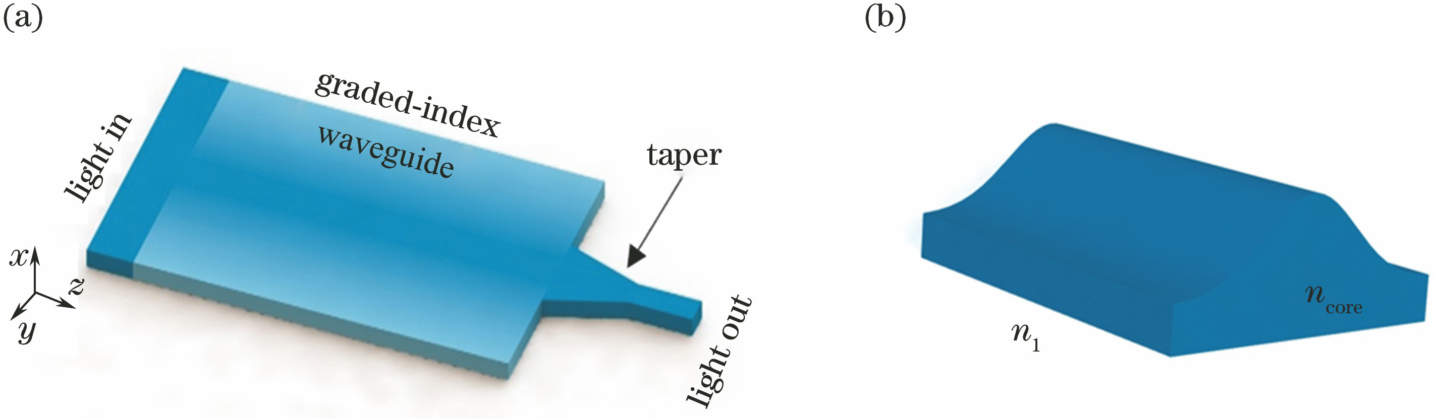
Fig. 1. Structural diagram. (a) Graded-index spot-size converter; (b) nonlinear-edge waveguide
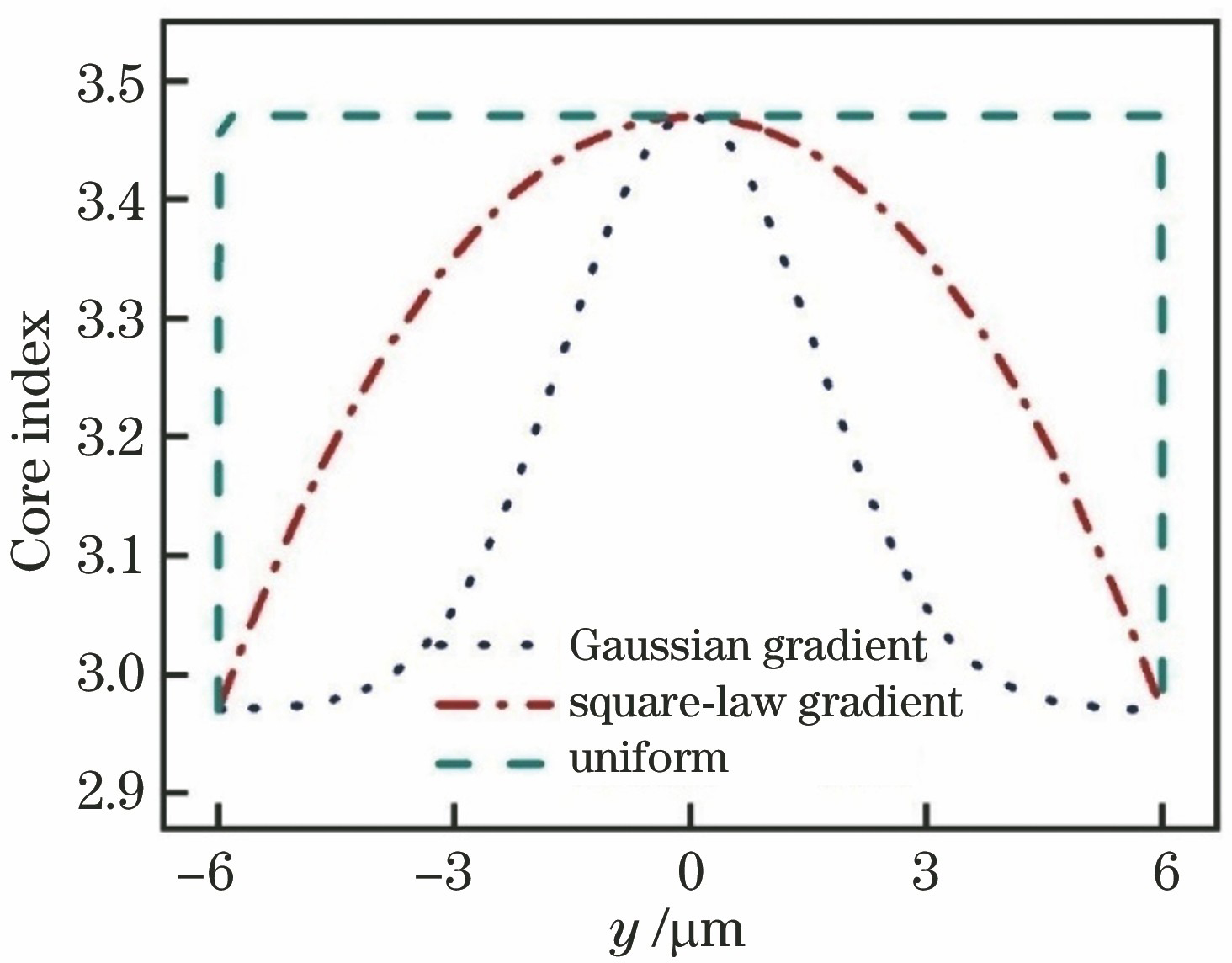
Fig. 2. Distribution of core-layer refractive index
Fig. 3. Fundamental mode fields of waveguides under different refractive index distributions. (a) Uniform waveguide; (b) Gaussian graded-index, Δ=0.5; (c) square-law graded-index, Δ=0.5; (d) square-law graded-index, Δ=0.1
Fig. 4. Self-focusing length and mode power proportion of spot-size converter. (a) Relationship between refractive indexdifference and self-focusing length; (b) normalized power proportion of each mode at input port
Fig. 5. Field patterns at self-focusing point under different refractive index distributions. (a) Gaussian distribution; (b) square-law distribution
Fig. 6. Electric fields for self-focusing effect under different refractive index distributions. (a) Gaussian distribution; (b) square-law distribution
Fig. 7. Structural diagram of taper
Fig. 8. Analysis of transmissivity. (a) Relationship between transmissivity and taper length; (b) relationship between transmissivity and taper width
Fig. 9. Electric field distribution
Fig. 10. Insertion loss and return loss versus wavelength. Note: bandwidth curves of insertion loss from the proposed spot-size converter and one in Ref. [3] are overlapped

Set citation alerts for the article
Please enter your email address
© Copyright 2018-2021 | Chinese Laser Press. All Rights Reserved 沪ICP备15018463号-20