
Xuetao Gan, Jianlin Zhao. Resonance Lineshapes in Optical Cavity[J]. Acta Optica Sinica, 2021, 41(8): 0823007
- Acta Optica Sinica
- Vol. 41, Issue 8, 0823007 (2021)
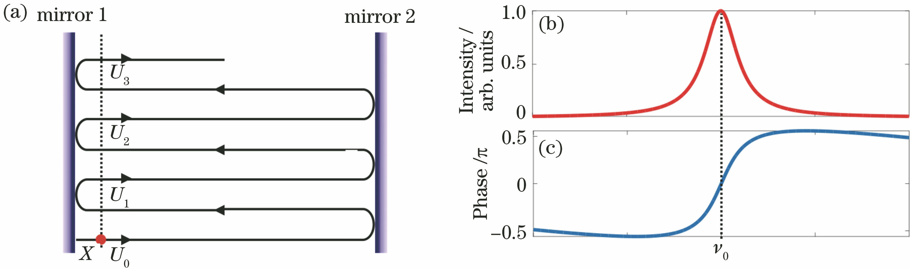
Fig. 1. Resonance mode in optical cavity. (a) Circulation of light wave in a Fabry-Pérot cavity; (b) intensity of the resonant mode; (c) phase of the resonance mode
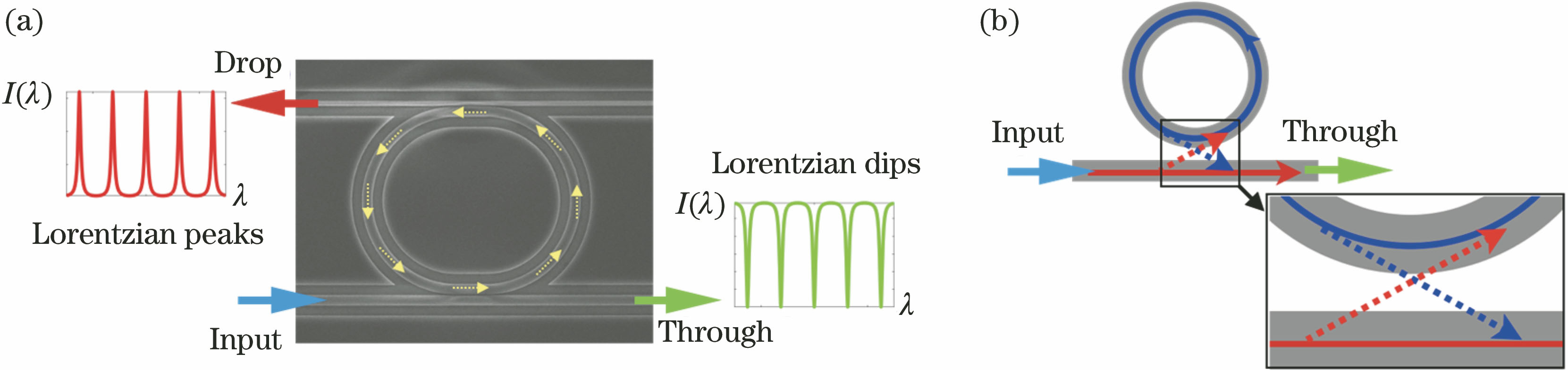
Fig. 2. Transmission spectra and lightwave coupling in the coupled waveguide-microring resonator. (a) Schematic of transmission spectra from the ‘Through’ and ‘Drop’ ports of the waveguides coupled with the microring resonator; (b) lightwave coupling between waveguide and microring resonator
Fig. 3. Different resonance lineshapes of microring resonators. (a) Structure and corresponding spectra of channel waveguide coupled with multiple microring cavities[3]; (b) structure and corresponding spectra of two microrings coupling[4]
Fig. 4. Fano resonance lineshapes with different q factors
Fig. 5. Analysis of resonance lineshape in traditional coupled waveguide-microring resonator. (a) Optical field distribution of resonant mode, guided wave mode, and coupling mode in traditional waveguide-microring resonator coupling structure[20]; (b) transmission spectrum in traditional waveguide-microring resonator coupling structure
Fig. 6. Analysis of resonance lineshape in waveguide-microring coupling structure with extra phase delay. (a) Optical field analysis of microring resonant mode, waveguide guided mode, and their coupling mode[20]; (b) modulation of transmission spectrum resonance lineshape of waveguide-microring cavity coupling structure by extra phase delay
Fig. 7. Experimental realization of different resonance lineshapes in the coupled waveguide-microring resonators. (a) Schematic of the experimental design for realizing a phase delay on a waveguide-microring coupling structure; (b) optical microscope image of a fabricated waveguide-microring structure[20]; (c) transmission spectra of the waveguide-microring structures without air-hole and with air-holes of different dimensions[20]
Fig. 8. Experimental verification of the modulated resonance lineshapes in the coupled waveguide-microring by the phase-delay. (a) Schematic of the device with an air-hole inside waveguide-microring coupling region; (b) schematic of the device with an air-hole outside waveguide-microring coupling region; (c) scanning electron microscope images and measured transmission spectra of the waveguide-microring device with the air-hole locating at different positions[21]
Fig. 9. Mode analysis and structures for realizing asymmetric Fano resonance lineshapes in microring resonators. (a) Device of a microring cavity coupled with one arm of Mach-Zehnder interferometer[23]; (b) device of a microring cavity inserted in a Mach-Zehnder interferometer[24]; (c) device of a microring cavity coupled with a feedback waveguide[25]; (d) schematic of microring cavity coupled with one arm of Mach-Zehnder interferometer and mode coupling analysis
Fig. 10. Analysis of different resonance lineshapes from two coupled optical resonators. (a) Schematic of the coupled structure between a channel waveguide and two optical cavities; (b) spectral feature of two overlapped resonance modes with different Q factors; (c) resonance lineshapes of two overlapped resonance mode with different Q factors when their resonance wavelengths have different relative locations

Set citation alerts for the article
Please enter your email address
© Copyright 2018-2021 | Chinese Laser Press. All Rights Reserved 沪ICP备15018463号-20