1Nanophotonics Research Centre, Institute of Microscale Optoelectronics & State Key Laboratory of Radio Frequency Heterogeneous Integration, Shenzhen University, Shenzhen 518060, China
2Research Center for Humanoid Sensing, Zhejiang Laboratory, Hangzhou 311100, China
A new type of power-exponent-phase vortex-like beams with both quadratic and cubic azimuthal phase gradients is investigated in this work. The intensity and orbital angular momentum (OAM) density distributions are noticeably different when the phase gradient increases or decreases along the azimuth angle, while the orthogonality and total OAM remain constant. The characteristics of the optical field undergo a significant change when the phase shifts from linear to nonlinear, with the variation of the power index having little impact on the beam characteristics under nonlinear phase conditions. These characteristics provide new ideas for applications such as particle manipulation, optical communications, and OAM encryption.
In 1992, Allen et al. discovered orbital angular momentum (OAM) in Laguerre–Gaussian beams[1]. Light carrying OAM has a helical phase structure that can be described using , where is the azimuth angle, and denotes the topological charge. The optical vortex beam (OV), with its unique spiral phase wavefront structure and zero light intensity distribution at its center[2], holds great potential for applications in optical manipulation[3-5], free-space optical communications[6-8], quantum communications[9-11], high-security encryption[12-14], among other fields. Multiplexing of OAM channels can add unlimited transmission capacity to optical communications[8,15,16]. For example, the combination of OAM multiplexing with polarization-division multiplexing and wavelength-division multiplexing, taking advantage of the orthogonal nature of OAM, can achieve ultra-high-capacity communication[17,18].
The conventional OV has a uniform distribution of OAM, which limits its application in scenarios such as particle manipulation. Various modulation methods have been explored for OV carrying OAM, such as using multi-channel superposition to obtain composite beams[19,20], metasurface generation, and manipulation of vortices[21,22]. Recently, some more unconventional vortex beams have been proposed, such as the power-exponent-phase vortex (PEPV) beams[23-25], multiplexed generalized vortex beams[26,27], and the generation of multi-twisted beams via azimuthal shift factors[28]. Although some studies have demonstrated that phase gradients (PGs) can generate optical force[29], research on the unique effects of different PG directions on vortex beams is severely limited. This greatly limits the widespread application of special vortex beams in fields such as optical communication, particle manipulation, and trapping.
In this work, we consider PEPV-like beams (PLBs) whose PG either increases or decreases along the azimuth. PLBs can be generated by simply imposing a gradient phase on a Gaussian laser mode (e.g., by using a spatial light modulator). We experimentally verify the intensity distribution of the PLBs and analyze their OAM density, orthogonality, and total OAM. As the PG direction along the azimuth angle increases or decreases, the intensity and OAM density distributions of PLBs exhibit noticeable differences while maintaining constant orthogonality and total OAM. Additionally, we discuss the quadratic and cubic changes in phase, as well as single-period and multi-period scenarios. This could offer more solutions for light field regulation, with potential applications including high-capacity communications, vortex information encryption, and particle manipulation.
Sign up for Chinese Optics Letters TOC. Get the latest issue of Chinese Optics Letters delivered right to you!Sign up now
2. Design Method
First, we consider the conventional OVs, for which the phase distribution is where is the topological charge, is the azimuthal angle, ranging from 0 to . For conventional OVs, the phase varies linearly with respect to change in angle. Here, we consider the case where the phase is the square or cube of the azimuth, which can be expressed as[23]
The case where is equal to two is called the quadratic OAM (QO), and the case where is equal to three is called the cubic OAM (CO). Note that if , single-period PLBs regress to conventional OVs. Building on this, we examine the phase of periodic variations. In this instance, the topological charge in this case is equal to the number of periods in the †range, i.e., . The phase distribution is
The situation where is equal to two is known as periodic QO (PQO), while the situation where is equal to three is referred to as periodic CO (PCO). Here, we define the direction from 0 to along the azimuth as positive. Therefore, the PG that increases along the azimuth is referred to as the positive gradient phase (PGP), while the PG that decreases along the azimuth is , known as the negative gradient phase (NGP). Both PGP and NGP cases are considered for both single-period and multi-period configurations.
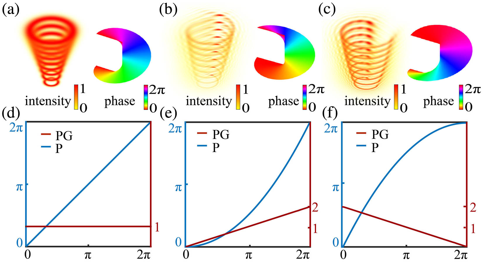
To investigate the effect of the two-phase gradient (PGP and NGP) generated by a PLB on beam propagation, we begin with the generalized laws of refraction[30,31]: where represents the PG along the angular direction. Here, we consider the case where the light is perpendicularly incident on a circular metasurface, and, in the cylindrical coordinate system, Eq. (4) then becomes where represents the off-axis angle of incident light passing through the metasurface with an additional gradient phase. This means that the gradient phase causes the ray to deviate with a deflection angle that is proportional to the PG . We can thus obtain the beam profile in the target observation plane as [26]. Consequently, for traditional OVs, the PG remains constant, and at each in the incident plane, the detection plane has the same , i.e., the light intensity is distributed evenly along the angular direction in a doughnut shape. In contrast, for PLBs, the PG will cause the target plane to have different values along the angular direction. Figure 1 schematically shows these differences. The phase of the PLB varies in two quadratic forms of PGP and NGP, as shown in Figs. 1(e) and 1(f), respectively. The PGP and NGP lead to distinct helical shapes, corresponding to Figs. 1(b) and 1(c), respectively.
Figure 1.Differences between OVs and PLBs. (a) Intensity and phase distributions of OAM. (b), (c) Intensity and phase distributions of PLBs. (d) Phase (P) and phase gradient (PG) of the OAM. (e), (f) P and PG of QO.
Numerical simulations were performed using a customized MATLAB script of Fresnel diffraction, and the PLBs with PGP and NGP distributions in single and multi-period cases are verified by experiments, as shown in Figs. 2 and 3. The top row of each figure displays the phase distribution, with blue lines indicating the phase (P) and red lines indicating the PG. The fourth row of each figure presents the simulated far-field intensity distribution, while the fifth row shows the experimental far-field intensity distribution. In our experiment, this nonlinear phase was applied to a Gaussian beam using a spatial light modulator, and the output light was received by a CCD camera (see Note 1 in the Supplementary Material for details).
Figure 2.Intensity profiles, phase distributions, and OAM density distributions of the (a), (b) QO and (c), (d) CO with different topological charges. (a), (c) The PG is increasing along the azimuth angle. (b), (d) The PG is decreasing along the azimuth angle. Further information regarding different topological charges can be found in Note 2 in the Supplementary Material.
Figure 3.Intensity profiles, phase distributions, and OAM density distributions of the (a), (b) PQO and (c), (d) PCO with different topological charges. (a), (c) The PG is increasing along the azimuth angle. (b), (d) The PG is decreasing along the azimuth angle. Further information regarding different topological charges can be found in Note 2 in the Supplementary Material.
A multi-period can be regarded as the superposition of multiple single-period distributions along the angular direction. It is worth noting that when the topological charge is one, the multi-period configuration degenerates into a single-period configuration. According to Eqs. (2) and (3), the phase distribution exhibits rotational symmetry in the case of multi-periods but not in the case of a single period. Consequently, as illustrated in Figs. 2 and 3, the intensity distribution displays rotational symmetry in the multi-period case but not in the single-period case. Another significant difference is that, in the single-period case, the PG is discontinuous only at 0 and , regardless of the topological charge L. In contrast, in the multi-period case, the discontinuities of the PG increase proportionally to the topological charge. As a result, the far-field intensity distribution in a single period has only one discontinuous point, while the multi-period case has several.
Figures 2 and 3 depict PGP and NGP as (a), (c) and (b), (d), and and as (a), (b) and (c), (d), respectively. Experimental results demonstrate excellent agreement between measured and predicted profiles in all cases. For PGP, a closed loop that resembles an Archimedean spiral appears in a single period, and a windmill shape that is proportional to the topological charge with a radius that increases from small to large appears within each small period in a multi-period. In contrast, the NGP’s PG is opposite to that of the PGP, which results in a distinct intensity contour. It exhibits an open loop similar to that of an Archimedean spiral in a single period with a periodic distribution from a large to small radius within each small period in a multi-period. A sudden change in the intensity distribution occurs from power index to , while and correspond to similar spiral distribution types. In other words, the intensity changes significantly only when the PG changes from linear to nonlinear, and the power index only affects the rate of change of the spiral radius , i.e., the change rate of the PG, with little influence on the intensity distribution. Furthermore, as the topological charge increases, the size of the intensity profile also increases. Thus, the law that the intensity distribution is determined by the topological charge of traditional OVs is applicable to PLBs as well (see Note 2 in the Supplementary Material for details).
One important parameter of the vortex beam is the OAM. The OAM of light is caused by the angular phase distribution of the light field and represents the wavefront properties of the beam. We calculated the OAM densities for all cases discussed above using a computer. The time-averaged Poynting vector is given by[32]where is the free-space permittivity, is the angular frequency, and is the wave number. The angular momentum density of a beam propagating along the Z axis can be expressed as[33]
Therefore, the component of the OAM density distribution is proportional to the component of the Poynting vector. By substituting into Eq. (6) we get
Using these equations, we can calculate the OAM density of the field. If the PG is constant, the OAM density is not affected by the azimuthal angle and is directly proportional to the topological charge. However, if the PG is a nonlinear function of the azimuthal angle, the OAM density is positively correlated with both the azimuthal angle and the topological charge. The theoretical OAM density is shown in the second row of Figs. 2 and 3. PLBs have an uneven OAM density distribution along the angular direction that follows the intensity distribution. This pattern is similar to that of traditional OVs, which also exhibit OAM density associated with the intensity distribution (see Note 2 in the Supplementary Material for details).
Here, we calculate the total OAM of different topological charges of PLBs as follows: where is the free-space permittivity, and is the angular frequency. Figure 4 shows the OAM for light fields with different topological charges. Regardless of whether it is a single period or a multi-period, the total OAM under PGP and NGP is similar to that of traditional OAM. In other words, PLBs with different PG directions do not alter the total OAM, but they do alter the distribution of OAM density.
Figure 4.Total OAM for light fields with different topological charges. (a) Total OAM of different topological charges for QO (red line), CO (blue line), and conventional OVs (black line). (b) Total OAM of different topological charges for PQO (red line), PCO (blue line), and conventional OAM (black line). The solid line indicates PGP, while the dashed line represents NGP.
Another important characteristic of OVs that is applied in optical communications is the strong orthogonality between beams with different topological charges. Clearly, any two vortex beams with different topological charges are orthogonal to each other. To verify the orthogonality property of PLBs, we integrate the inner product of any two beams. Figure 5 illustrates the orthogonality of the vortex beam under NGP conditions. The orthogonality of OAM between different topological charges ranging from to 10 is presented, where the unit for the numbers in the figure is decibels (dB). Higher dB values indicate better orthogonality. The results (see Note 4 in the Supplementary Material for details) clearly indicate that the orthogonality of the beams is not affected by PGP and NGP, and all types of PLBs exhibit a certain degree of orthogonality. However, compared to traditional OVs, their orthogonality is weaker. The reason for this difference is that the PG of PLBs is not constant, meaning that beams with different topological charges have the same PG in some partial area.
Figure 5.Orthogonality between different topological charges of NGP vortex beams for QO, CO, PQO, and PCO, respectively. Further information about PGP vector beams can be found in Note 4 in the Supplementary Material.
In summary, we have proposed a special vortex beam with a PG that increases or decreases along the azimuthal variation, and we have analyzed its optical properties. Our experimental results confirm the theoretical predictions of the PLBs. Due to their PG changing in opposite directions, they exhibit spiraling intensity and OAM density distributions, while maintaining orthogonality and total OAM. Furthermore, we discussed the impact of the power index on optical field characteristics, noting that it only causes a sudden change in these characteristics when the PG shifts from linear to nonlinear. The beam characteristics of PLBs with and showed minimal variation. Additionally, PLBs can generate unique optical forces, which will be discussed in our subsequent research. These unique intensity profiles of the PLBs may provide new avenues for various optical applications, including optical manipulation and optical communication. As a result, PLBs offer greater application flexibility than traditional OVs.