• Photonics Research
  • Vol. 10, Issue 3, 711 (2022)
Xinglin Zeng1、*, Wenbin He1, Michael H. Frosz1, Andreas Geilen1, Paul Roth1, Gordon K. L. Wong1, Philip St.J. Russell1, and Birgit Stiller1、2
Author Affiliations
  • 1Max-Planck Institute for the Science of Light, 91058 Erlangen, Germany
  • 2Department of Physics, Friedrich-Alexander-Universität, 91058 Erlangen, Germany
  • show less
    DOI: 10.1364/PRJ.443706 Cite this Article Set citation alerts
    Xinglin Zeng, Wenbin He, Michael H. Frosz, Andreas Geilen, Paul Roth, Gordon K. L. Wong, Philip St.J. Russell, Birgit Stiller. Stimulated Brillouin scattering in chiral photonic crystal fiber[J]. Photonics Research, 2022, 10(3): 711 Copy Citation Text show less

    Abstract

    Stimulated Brillouin scattering (SBS) has many applications; for example, in sensing, microwave photonics, and signal processing. Here, we report the first experimental study of SBS in chiral photonic crystal fiber (PCF), which displays optical activity and robustly maintains circular polarization states against external perturbations. As a result, circularly polarized pump light is cleanly backscattered into a Stokes signal with the orthogonal circular polarization state, as is required by angular momentum conservation. By comparison, untwisted PCF generates a Stokes signal with an unpredictable polarization state, owing to its high sensitivity to external perturbations. We use chiral PCF to realize a circularly polarized continuous-wave Brillouin laser. The results pave the way for a new generation of stable circularly polarized SBS systems with applications in quantum manipulation, optical tweezers, optical gyroscopes, and fiber sensors.

    1. INTRODUCTION

    First observed in bulk materials by Chiao, Townes, and Stoicheff in 1964 [1], stimulated Brillouin scattering (SBS) is a nonlinear optical process in which light is backscattered by a hypersonic acoustic wave. The Doppler-shifted backward signal beats with the pump light, creating a moving interference pattern that in turn amplifies the acoustic wave, leading to strong amplification of the backward signal for high enough pump power. Since its first demonstration, SBS has been explored and exploited in many different systems, especially optical fibers [2] and integrated photonics [3]. Among the many applications of SBS are narrow linewidth lasers [4], fiber sensors [5], light storage systems [6], and microwave photonic filters [7]. To date, to the best of our knowledge, SBS has not been studied in chiral photonic crystal fibers (PCFs), where the core microstructure rotates with the position along the fiber axis.

    Studies of SBS in nonchiral PCFs with high air-filling fractions and very small cores have revealed how tight confinement of acoustic vibrations gives rise to SBS frequency shifts not seen in standard step-index fibers [8,9]. In recent years, chiral PCF, drawn from a spinning preform, has emerged as a unique platform to study the behavior of light in chiral structures that are infinitely extended in the direction of the twist [10]. Such structures are very difficult, if not impossible, to realize on an integrated photonic chip. Chiral PCF has been shown to robustly preserve a circular polarization state over long distances, allowing the investigation of nonlinear processes in the presence of chirality [11,12]. Although the polarization properties of SBS in nonchiral fibers have been investigated by many research groups [1316], it has so far, to the best of our knowledge, not been possible to observe SBS between clean circularly polarized modes.

    Here, we report the first experimental study of SBS in chiral PCF, demonstrating both Brillouin amplification of circularly polarized light, and a continuous-wave (CW) circularly polarized Brillouin laser. The results are of potential interest in fiber-optic current sensing [17], fiber-optic gyroscopes [18], and teleportation of quantum states [19].

    2. CHIRAL PHOTONIC CRYSTAL FIBER

    Figure 1(a) shows a 3D sketch of a chiral PCF. Figure 1(b) shows a scanning electron microscopy (SEM) image of the microstructure of the chiral PCF used in the experiments. The chiral PCF was designed to support only a nondegenerate pair of circularly polarized fundamental modes. It was fabricated from fused silica using the standard stack-and-draw technique. The helical pitch was 1.6 cm, created by spinning the preform during the fiber draw, and the circular birefringence BC was measured to be 2.134 μRIU at 1550 nm [Fig. 1(c)], which agrees well with the results of finite element method (FEM). (For more details, see Appendix A.) The inset in Fig. 1(c) shows the simulated distribution of the Poynting vector for the left circularly polarized (LCP) fundamental mode. Due to the nondegeneracy, the measured Stokes parameters are (S1,S2,S3)=(0.27,0.17,0.95) and (S1,S2,S3)=(0.28,0.18,0.94) after the LCP and RCP modes propagate through 38 m chiral PCF, respectively.

    (a) 3D sketch of a chiral PCF. (b) SEM image of the PCF used in the experiments. The hollow channels have a diameter d=1.7 μm and spacing Λ=3.8 μm(d/Λ=0.45), and the core diameter is ∼6 μm. The LP01-like core modes have (measured) losses 0.06 dB/m (LCP) and 0.05 dB/m (RCP), and effective indices 1.435599 (LCP) and 1.435601 (RCP) at 1550 nm, yielding circular birefringence BC=2.134 μRIU. (c) Measured and calculated circular birefringence BC versus wavelength. The inset is the calculated distribution of the Poynting vector.

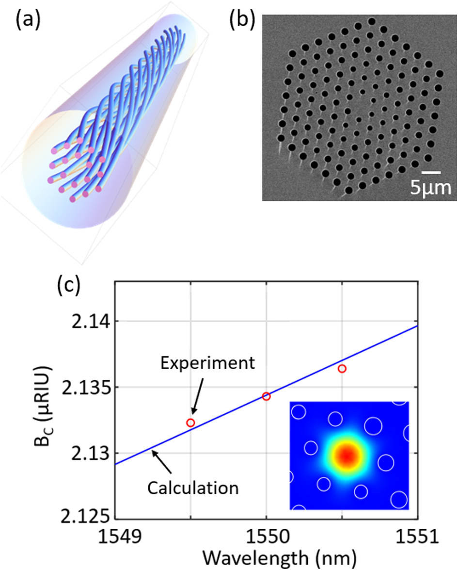
    Figure 1.(a) 3D sketch of a chiral PCF. (b) SEM image of the PCF used in the experiments. The hollow channels have a diameter d=1.7  μm and spacing Λ=3.8  μm(d/Λ=0.45), and the core diameter is 6  μm. The LP01-like core modes have (measured) losses 0.06 dB/m (LCP) and 0.05 dB/m (RCP), and effective indices 1.435599 (LCP) and 1.435601 (RCP) at 1550 nm, yielding circular birefringence BC=2.134  μRIU. (c) Measured and calculated circular birefringence BC versus wavelength. The inset is the calculated distribution of the Poynting vector.

    3. BRILLOUIN SCATTERING IN CHIRAL PCF

    Figure 2(a) shows the heterodyne detection setup for measuring Brillouin frequency in a chiral PCF. Both pump and local oscillator (LO) are derived from a narrow linewidth (<1  kHz) 1550 nm continuous wave (CW) laser by using a 90:10 fiber coupler. The pump wave is then boosted by an erbium-doped fiber amplifier (EDFA) and injected into the chiral PCF through an optical circulator. The circular polarization states are tuned by adjusting the fiber polarization controller (FPC) before the circulator. The thermal noise-initiated Stokes signal coming back from the PCF is delivered by the circulator and interferes with the LO by using the second 90:10 fiber coupler and the beating signal is detected by a photodetector (PD) and an electrical spectrum analyzer (ESA). Figure 2(b) shows the spontaneous Brillouin spectrum measured in a 38 m length of chiral PCF for a 0.9 W LCP pump, which is just below the threshold for SBS. Note that the SBS threshold is usually defined as the point at which the Stokes power equals 1% of the pump power [20]. It is clear that the Brillouin frequencies can always be distinguished whether the pump power is below or above the threshold. The peak at 10.82 GHz is an artifact caused by Brillouin scattering in SMF-28 after port 2 of the circulator, and the second peak at 11.013 GHz comes from the chiral PCF. Unlike PCFs with large d/Λ values and μm-scale cores, which support several hybrid torsional-radial acoustic modes [8], the PCF used here has a relatively low d/Λ (0.45) and a large core (diameter 6 μm), so that the Brillouin frequency shift is close to that obtained in bulk glass: 2nscL/λp=11.12  GHz, where ns is the refractive index of silica at the pump laser wavelength λp, and cL=5971  m/s is the longitudinal acoustic velocity. LCP and RCP pumps were found to generate almost identical Brillouin spectra.

    (a) Experimental setup to measure Brillouin frequencies in a chiral PCF. (b) Spontaneous Brillouin spectrum generated by pumping with 0.9 W of circularly polarized CW laser at 1550 nm. (c) Numerically calculated optoacoustic coupling coefficients (normalized) for different acoustic modes around 11 GHz. (d) Axial displacements (normalized to the square root of the power) of acoustic modes at 11.021 GHz and 11.039 GHz in (c).

    Figure 2.(a) Experimental setup to measure Brillouin frequencies in a chiral PCF. (b) Spontaneous Brillouin spectrum generated by pumping with 0.9 W of circularly polarized CW laser at 1550 nm. (c) Numerically calculated optoacoustic coupling coefficients (normalized) for different acoustic modes around 11 GHz. (d) Axial displacements (normalized to the square root of the power) of acoustic modes at 11.021 GHz and 11.039 GHz in (c).

    To confirm these results, we used FEM to calculate the normalized optoacoustic coupling coefficient, defined by [21]κ=|ELCERCpijklεkldxdy|ELCERC|dxdy|ε|2dxdy|2,where ELC(RC) are the scalar electric fields of circularly polarized pump and Stokes modes, pijkl is the elasto-optic tensor, and εkl is the strain tensor associated with the acoustic mode. Although the numerical results in Fig. 2(c) show that more than 500 acoustic modes are supported in the chiral PCF in the frequency range from 10.8 GHz to 11.2 GHz, only the modes at 11.02 GHz (close to the experimental peak at 11.013 GHz) and 11.039 GHz have a significant overlap with the optical modes, thus dominating the Brillouin scattering process. Although it was not possible to resolve the two closely spaced peaks by heterodyning, they could be detected when the Stokes signal was seeded, as discussed in Section 4. The calculated power-normalized axial displacements of the two acoustic modes in Fig. 2(d) show clearly that the mode at 11.02 GHz is more concentrated in the PCF core and so is expected to be dominant.

    We next increased the pump power to reach the SBS regime, when the polarization state of the much stronger Stokes signals could be more easily and precisely measured (Fig. 3). The CW pump light was amplified in an EDFA and its polarization state was controlled using a combination of polarizing beamsplitter (PBS) and quarter-wave (λ/4) plate. Backscattered signals with the same polarization state as the pump are transmitted by the PBS and detected by a power meter placed at port 3 of the circulator, while orthogonally polarized light is reflected and detected by a second power meter. The transmitted pump power is monitored by a third power meter. Narrowband (6 GHz) notch filters in the path of each Stokes signal are used to filter out Fresnel reflections and Rayleigh scattering. Figure 3(b) shows the power dependence of the Stokes and transmitted pump signals for LCP, RCP, and linearly polarized pump light. Above a threshold of 0.95  W, the orthogonally polarized Stokes signal grows rapidly with a slope efficiency of 50%, while the transmitted pump power saturates. The co-polarized Stokes signal shows no gain, as angular momentum conservation would otherwise be violated. (For more details, see Appendix C.)

    (a) Experimental setup to measure SBS threshold of different circularly polarized light in chiral PCF. EDFA, erbium-doped fiber amplifier; FPC, fiber-based polarization controller; and PBS, polarizing beamsplitter. (b) Stokes and transmitted pump power in a 38 m length of chiral PCF for LCP, RCP, and linearly polarized pump light (left to right).

    Figure 3.(a) Experimental setup to measure SBS threshold of different circularly polarized light in chiral PCF. EDFA, erbium-doped fiber amplifier; FPC, fiber-based polarization controller; and PBS, polarizing beamsplitter. (b) Stokes and transmitted pump power in a 38 m length of chiral PCF for LCP, RCP, and linearly polarized pump light (left to right).

    These results confirm robust maintenance of circular polarization states and conservation of spin during Brillouin scattering in chiral PCF. More interestingly, when a linearly polarized pump is injected into the chiral PCF, the polarization state of the backscattered Stokes wave is also linearly polarized and has the same azimuthal angle as that of the pump, as shown in far right figure in Fig. 3(b). We attribute this to well-controlled optical activity in the chiral PCF, which causes the linearly polarized pump and backward Stokes modes to be co-polarized at all points along the fiber. (For more details, see Appendix D.) The SBS threshold power in all the three cases was 0.95  W; i.e., it is independent of the polarization state.

    To assess the robustness of polarization maintenance, the Stokes signal powers and Stokes polarization states were measured for LCP and RCP pump light with the fiber spooled to diameters of 50 and 16 cm (Table 1). The pump power was kept constant at 2.45 W in all the measurements. The modulus of the Stokes parameter S3 is |S3|=|PRCPLCPRC+PLC|,which was greater than 0.98 for both LCP and RCP pump light in the 50 cm spool, corresponding to an LCP to RCP power extinction ratio of better than 23 dB. For the 16 cm spool, the S3 was 0.88, corresponding to a somewhat lower extinction ratio of 12 dB. Bending causes the guided eigenmodes to become elliptically polarized, which naturally affects the Brillouin signals. Due to the loss of pump and Stokes wave in the fiber, the input pump power is larger than the sum of total Stokes power and output pump power.

    Signal Powers and Stokes Parameter |S3| in Chiral PCF Spooled to Different Diametersa

    LCP Stokes (mW)RCP Stokes (mW)Trans. Pump (mW)|S3|
    SD=16cmSD=50cmSD=16cmSD=50cmSD=16cmSD=50cmSD=16cmSD=50cm
    LCP pump4437206936286320.8850.991
    RCP pump6186673846416520.8840.988

    Pump power is 2.45 W. SD, spool diameter (in cm).

    To illustrate the striking contrast between chiral and nonchiral PCFs, we carried out the same experiment using a 25 m long untwisted PCF with a closely similar microstructure. The fiber loss was 0.012 dB/m and its slightly two-fold rotationally symmetric structure [Fig. 1(b)] resulted in a linear birefringence BL=12.5  μRIU at 1550 nm. Due to degeneracy between two circular polarization states, the measured Stokes parameters are (S1,S2,S3)=(0.37,0.74,0.56) and (S1,S2,S3)=(0.11,0.8,0.58) after the LCP and RCP modes propagate through 25 m nonchiral PCF, respectively. Figure 4 shows the measured Stokes power as a function of input pump power. The shorter fiber length and the poor polarization state maintenance resulted in an SBS threshold power that was twice as high. In sharp contrast to chiral PCF, both the LCP and RCP Stokes signals grow in power together, which we attribute to the evolution of the pump polarization state, which in a straight fiber will go through a full cycle of LCP-linear-RCP-linear every λ/BL12  cm.

    Stokes signal powers measured in a 25 m length of untwisted PCF, pumped by LCP, RCP, and linearly polarized light.

    Figure 4.Stokes signal powers measured in a 25 m length of untwisted PCF, pumped by LCP, RCP, and linearly polarized light.

    4. BRILLOUIN AMPLIFICATION IN CHIRAL PCF

    We now investigate Brillouin amplification of circularly polarized light using a 2 m length of chiral PCF. The amplified Stokes signal takes the well-known form PS(0)=PS(L)exp[gBPP(1eαL)/ααL],where gB is the Brillouin gain coefficient, α is the fiber loss, L is the fiber length, and PP is the pump power. Details of the experimental setup are available in Appendix E. Figure 5(a) shows the Brillouin gain for a varying pump-seed frequency difference at a pump power of 1 W and a Stokes seed power of 10 mW. As expected, the Brillouin gain is significant only when the pump and seed are orthogonally polarized, reaching peak values of 0.82  W1m1 for an LCP/RCP pump/seed and 0.9  W1m1 for the reverse. The gain spectra deviate slightly from perfect Lorentzians, but can be fitted to two Lorentzians, which we attribute to the two acoustic modes shown in Fig. 2(c). The double Lorentzian fits very well with the experimental results, with central frequencies 11.01 GHz and 11.044 GHz in excellent agreement with the numerical calculations (11.02 GHz and 11.039 GHz).

    (a) Measured Brillouin gain spectra (FWHM 41 MHz) when pumping with LCP (left) and RCP (right) light. The circles are measured data, and the full red line is a fit based on two Lorentzians (FWHM 31 and 65 MHz), indicated by the dashed red lines. (b) Left: Stokes gain spectra for LCP pump powers 0.54 W, 0.86 W, 1.36 W, and 2.09 W. Right: peak Stokes gain as a function of LCP pump power. The circles are the experimental data points and the line is a linear fit.

    Figure 5.(a) Measured Brillouin gain spectra (FWHM 41 MHz) when pumping with LCP (left) and RCP (right) light. The circles are measured data, and the full red line is a fit based on two Lorentzians (FWHM 31 and 65 MHz), indicated by the dashed red lines. (b) Left: Stokes gain spectra for LCP pump powers 0.54 W, 0.86 W, 1.36 W, and 2.09 W. Right: peak Stokes gain as a function of LCP pump power. The circles are the experimental data points and the line is a linear fit.

    The peak gain coefficients of the two Lorentzians are 0.745  W1m1 and 0.15  W1  m1 for LCP pumping, and 0.794  W1m1 and 0.184  W1m1 for RCP pumping, which are again close to the theoretical values of 0.851  W1m1 and 0.256  W1m1, respectively. (For details, see Appendix B.) The linewidth of the fitted Lorentzian gain spectrum is 31 MHz for the stronger acoustic mode and 65 MHz for the weaker one, yielding an effective gain linewidth of 41 MHz for both pumping configurations. The gain at four different LCP pump powers is plotted versus frequency in the left-hand panel in Fig. 5(b), and versus pump power in the right-hand panel, showing a slope efficiency of 5.67 dB/W.

    5. CIRCULARLY POLARIZED BRILLOUIN LASER

    Next, we constructed a circularly polarized Brillouin laser by placing a 2 m length of chiral PCF in a ring cavity [Fig. 6(a)]. A CW pump light was launched into the laser cavity through a polarizing beamsplitter and a λ/4 plate to generate a circularly polarized signal. Since the Stokes signal is orthogonal to the pump, it is reflected by the polarizing beamsplitter and thus circulates inside the cavity. A λ/4 plate and a polarizer are used to block the transmitted pump light, while letting the backward Stokes signal propagate freely. A beamsplitter is used to couple 10% of the Stokes signal out of the cavity, so that its polarization state can be measured. The laser spectrum, threshold, and linewidth were measured by an optical spectrum analyzer (OSA), a power meter, and by self-heterodyning. The total cavity length is 4 m (2 m chiral PCF and 2 m free space), yielding a free spectral range of 30.8 MHz. The cavity length was adjusted so that a single cavity mode coincided with the maximum Brillouin gain. Given the 41 MHz FWHM Brillouin gain linewidth and strong mode competition, this meant that only one cavity mode participated in lasing.

    (a) Experimental setup of circularly polarized Brillouin laser. (b) Laser power as a function of pump power for LCP (blue circles) and RCP (red crosses) pump light. (c) Theoretically fitted (blue) and measured (red) laser spectrum from sub-coherence delayed self-heterodyne system. Four sharp side peaks around the center peak is from the artifacts of the pump laser and unrelated to the experimental result. The inset is the spectrum of spontaneously scattered Stokes light from the identical chiral PCF and the linewidth-narrowed intracavity laser spectrum measured by delayed self-heterodyne system (the axis labels are same as those of the main figure).

    Figure 6.(a) Experimental setup of circularly polarized Brillouin laser. (b) Laser power as a function of pump power for LCP (blue circles) and RCP (red crosses) pump light. (c) Theoretically fitted (blue) and measured (red) laser spectrum from sub-coherence delayed self-heterodyne system. Four sharp side peaks around the center peak is from the artifacts of the pump laser and unrelated to the experimental result. The inset is the spectrum of spontaneously scattered Stokes light from the identical chiral PCF and the linewidth-narrowed intracavity laser spectrum measured by delayed self-heterodyne system (the axis labels are same as those of the main figure).

    The spectrum measured by the OSA just before the filter confirmed the presence of a lasing signal with frequency 11.013 GHz below the pump frequency. (For details, see Appendix E.) The laser power is plotted against the LCP and RCP pump power in Fig. 6(b). Lasing commences when the Brillouin gain exceeds the 4.12 dB round-trip loss of the laser cavity (beamsplitter 1 dB; fiber coupling 1.5 dB; fiber loss 0.12 dB; polarization components 1.5 dB). The threshold powers are 800  mW for both LCP pumping (slope efficiency 7.5%) and RCP pumping (slope efficiency 7.6%). We attribute the tiny difference in slope efficiency in the two cases to a slight circular dichroism in the propagation loss. The Brillouin laser spectrum measured by delayed self-heterodyning [22] is shown in Fig. 6(c). (For details, see Appendix F.) The laser spectrum is also compared in the inset of Fig. 6(c) with the spontaneous Stokes spectrum generated in an identical chiral PCF in the absence of optical cavity feedback, showing a line-narrowing factor of 5×10⁴, from 31  MHz to 660 Hz. The laser output power is stable, with fluctuations of <1% over 1 h. Mode hopping (in the 1 MHz range) nevertheless constantly occurs, since the lasing cavity is neither covered nor isolated from the environment.

    We note that lasers with a sub-kHz linewidth have a coherence length of greater than 100 km, and the decoherent self-heterodyning requires the SMF in reference path to be longer than that. Such a long fiber transmission will induce Gaussian noise on the laser spectrum. To precisely measure the Brillouin laser linewidth, we applied a “sub-coherence” self-heterodyne technique using a 2 km length of single-mode fiber as a delay line, so that the path difference was less than the laser coherence length and the laser spectrum has less Gaussian noise. The exact laser linewidth of 660 Hz is then obtained by fitting the measured spectrum to the sub-coherence lineshape function [Fig. 6(c)].

    6. CONCLUSIONS

    Chiral PCF, drawn from a spinning preform, robustly maintains the spin of guided light and therefore may be used for stimulated Brillouin scattering with circularly polarized light. Conservation of the angular momentum means that significant gain is only possible when the Stokes and pump signals are orthogonally polarized. Brillouin amplifiers and lasers for circularly polarized light can be successfully realized using a chiral PCF as the gain medium. When, in contrast, a nonchiral PCF is used, the polarization states of the Stokes and transmitted pump signals are unpredictable.

    To the best of our knowledge, this is the first report of SBS in circularly birefringent chiral fiber. We note that chiral fibers with off-center [23] or coupled cores [24] can also display circular birefringence, although fibers with two-fold rotational symmetry, such as twisted polarization-maintaining fiber (PMF) [25], support elliptically polarized eigenmodes. Twisted multicore PCFs with N-fold rotational symmetry (N>2) can guide vortex modes with a nonzero topological charge, and can be used in SBS [26]. Chiral SBS has many potential applications that include fiber sensing [17,27], optical tweezers [28], Brillouin laser gyroscopes [29], and quantum manipulation [19].

    Acknowledgment

    Acknowledgment. The authors thank Yang Chen, Jennifer Hartwigs, and Jiapeng Huang for help with several aspects of theory and experiments.

    APPENDIX A: SIMULATIONS OF OPTICAL AND ACOUSTIC MODES

    The finite element method (FEM) simulations were based on an SEM image of the fiber structure. To increase the accuracy, the mesh density was increased within the core area. The hollow channel diameter d is 1.7  μm and interhole spacing Λ is 3.8  μm, yielding d/Λ=0.45, which is close to the condition for endless single-mode operation [30]. The fiber structure is slightly asymmetric, with core widths varying from 6.16 to 5.86 μm. Figure 7(a) shows the simulated mode profiles and refractive indices of left circularly and right circularly polarized modes. The effective mode area of both modes is 24.6  μm2.

    (a) Calculated normalized electric fields and effective indices for LCP and RCP modes. (b) Calculated axial displacements and frequencies for two acoustic modes that contribute to the backward Brillouin scattering in the chiral PCF.

    Figure 7.(a) Calculated normalized electric fields and effective indices for LCP and RCP modes. (b) Calculated axial displacements and frequencies for two acoustic modes that contribute to the backward Brillouin scattering in the chiral PCF.

    Figure 7(b) shows the axial displacements of two acoustic modes with the highest acousto-optic overlap, which was calculated using the COMSOL Solid Mechanics module. Two different acoustic modes satisfy the phase-matching and energy conservation for SBS, at 11.021 GHz and 11.039 GHz. Due to the low d/Λ value for this PCF, these acoustic modes are not perfectly confined in the core. We assume that the acoustic amplitude distribution is relatively unaffected by the twist.

    APPENDIX B: ESTIMATE OF BRILLOUIN GAIN

    We can roughly estimate the gain coefficient using [2] g0=ωγe2neffνac3ρΓBAeffao,where ω is the light angular frequency, γe is the electrostrictive constant, neff is the effective index of the optical mode in the chiral PCF, c is the optical velocity in vacuum, ρ is the mean density of silica, νa is the longitudinal acoustic velocity, and ΓB/2π is the gain spectrum linewidth. For silica, γe=1.17, ρ0=2202  kg/m3, neff=1.4356, and νa=5970  m/s. In the experiment, ω=2π×193.414  THz; ΓB=2π×31  MHz for the acoustic mode at 11.01 GHz and ΓB=2π×65  MHz for the acoustic mode at 11.044 GHz. Aeffao is the acousto-optic overlap effective area and is defined by Aeffao=f2(x,y)2ξm2(x,y)ξm(x,y)f2(x,y)2,where f2(x,y) is the transverse optical intensity distribution and ξm(x,y) is the acoustic strain field. The brackets ⟨…⟩ represent overlap integrals over the fiber cross-section. The Aeffao are calculated as 24  μm2 and 38  μm2 for the two acoustic modes in Fig. 7(b). After inserting all the parameters into Eq. (B1), the calculated Brillouin gain coefficients are 0.851  W1m1 and 0.256  W1m1 for the two acoustic modes, which are very close to the measured values (0.745  W1m1 and 0.15  W1m1 for the LCP pump light, and 0.794  W1m1 and 0.184  W1m1 for the RCP pump).

    APPENDIX C: ANGULAR MOMENTUM CONSERVATION

    The forward-propagating pump mode in a chiral PCF takes the analytical form, EP(z,t)=A(x^+isPy^)ei(βPzωPt),where sP=±1 is the spin angular momentum (SAM, sP=+1 corresponding to left circular polarization). A backward-propagating Stokes mode similarly takes the form, ES(z,t)=B(x^isSy^)ei(βSz+ωSt),where the sign in front of sS is reversed to maintain the handedness of the xyz coordinate system. The acoustic density modulation may be written as ρ(z,t)=ρ0+ρmei(qzΩt),and the Brillouin gain is maximized when the energy and momentum are conserved; i.e., Ω=ωPωS and q=βP+βS. The overlap between the three waves is proportional to EPES*ρm*, which is nonzero only if sP=sS, which corresponds to sP(+z^)=sS(z^); i.e., conservation of SAM.

    APPENDIX D: POLARIZATION MAINTENANCE FOR LINEARLY POLARIZED PUMP

    When the pump light is linearly polarized, the circular birefringence of the chiral PCF causes optical activity (i.e., the direction of polarization rotates by 2πBC/λ radians per m). For BC=2.134×10⁶ and a Brillouin frequency shift of 11 GHz, the difference in the rotation rates between pump and Stokes is 0.49 radians per km or 1° over 38 m, the longest fiber length used in the experiments. As a result, we can assume that linearly polarized pump and Stokes fields remain co-polarized over the entire fiber length.

    APPENDIX E: MEASUREMENT OF BRILLOUIN AMPLIFICATION, GAIN, AND BRILLOUIN LASER SPECTRUM

    The Brillouin gain and spectrum were measured using a typical pump-seed setup with added polarization control, as shown in Fig. 8. Both pump and seed were derived from a narrow linewidth 1550 nm CW laser, the seed frequency being tuned using a single sideband modulator (SSBM). The pump signal was boosted by an EDFA and the polarization states of both pump and seed were controlled by fiber polarization controllers (FPCs) and measured using a polarimeter. The amplified seed power was measured at port 3 of the circulator using a filter.

    Experimental setup to measure Brillouin gain spectra of the chiral PCF. (Dashed line represents free space.)

    Figure 8.Experimental setup to measure Brillouin gain spectra of the chiral PCF. (Dashed line represents free space.)

    Power spectrum of the laser output before the narrowband filter, measured by the OSA. The lasing and back-reflected pump signals are clearly observed.

    Figure 9.Power spectrum of the laser output before the narrowband filter, measured by the OSA. The lasing and back-reflected pump signals are clearly observed.

    APPENDIX F: DELAYED SELF-HETERODYNE SETUP FOR LINEWIDTH MEASUREMENT

    Since grating-based OSAs and Fabry–Perot interferometers typically have insufficient resolution (a few GHz and tens of MHz, respectively), we employed delayed interferometric self-heterodyning to measure the Brillouin laser linewidth. Based on a Mach–Zehnder interferometer, this system can measure sub-kHz linewidths. The setup is shown in Fig. 10(a). The Brillouin laser output is launched into an SMF and split into two paths at a 3 dB fiber coupler. One path is frequency-shifted by 200 MHz using an acousto-optic modulator (AOM), and the other path is transmitted through a 2 km length of SMF, so that it becomes decorrelated from the frequency-shifted light. The two beams are then combined on a photodetector and the beat frequency (centered at 200 MHz) is observed using an electrical spectrum analyzer (ESA). A polarization controller is used in one of the arms to maximize the strength of the beat signal.

    (a) Experimental setup for delayed self-heterodyne measurement. (b) Experimentally measured self-heterodyne spectrum when the SMF delay is 26 km. (c) Experimentally measured self-heterodyne spectrum (red) and fitted curves (blue) with sub-coherent heterodyne formula [31] when the SMF delay is 2 km and 3 km.

    Figure 10.(a) Experimental setup for delayed self-heterodyne measurement. (b) Experimentally measured self-heterodyne spectrum when the SMF delay is 26 km. (c) Experimentally measured self-heterodyne spectrum (red) and fitted curves (blue) with sub-coherent heterodyne formula [31] when the SMF delay is 2 km and 3 km.

    Analysis of the resulting spectrum falls into two regimes: one for lasers with a coherence length shorter than or comparable with the SMF delay, and the other for lasers with a coherence length longer than the SMF delay (the sub-coherence domain). Ideally, the laser with a coherence length shorter than the imbalance delay will produce a Lorentzian line with a half-width-at-half-maximum equal to the laser linewidth. Due, however, to substantial Gaussian noise (pump noise, vibrations, and acoustic noise) during long SMF transmission, the resulting spectrum is a convolution of Gaussian and Lorentzian functions and has a complex Voigt profile, as shown in Fig. 10(b) (the measured Brillouin laser spectrum with 26 km path length imbalance). To measure the linewidth in the sub-coherence range, we used only a few km of SMF, in which case the self-heterodyne lineshape [31] will be a Dirac delta function at the AOM frequency, together with the interferometer transfer function, which displays many sidebands about its central frequency. Figure 10(c) shows the measured power spectra for SMF delay lengths of 2 km and 3 km. The side peaks close to the central delta function are caused by noise in the pump laser. A linewidth of approximately 0.6 kHz is obtained by fitting the measured data to a self-heterodyne lineshape function.

    References

    [1] R. Y. Chiao, C. H. Townes, B. P. Stoicheff. Stimulated Brillouin scattering and coherent generation of intense hypersonic waves. Phys. Rev. Lett., 12, 592-595(1964).

    [2] A. Kobyakov, M. Sauer, D. Chowdhury. Stimulated Brillouin scattering in optical fibers. Adv. Opt. Photon., 2, 1-59(2010).

    [3] B. J. Eggleton, C. G. Poulton, P. T. Rakich, M. J. Steel, G. Bahl. Brillouin integrated photonics. Nat. Photonics, 13, 664-677(2019).

    [4] S. P. Smith, F. Zarinetchi, S. Ezekiel. Narrow-linewidth stimulated Brillouin fiber laser and applications. Opt. Lett., 16, 393-395(1991).

    [5] X. Bao, L. Chen. Recent progress in Brillouin scattering based fiber sensors. Sensors, 11, 4152-4187(2011).

    [6] B. Stiller, M. Merklein, C. Wolff, K. Vu, P. Ma, S. J. Madden, B. J. Eggleton. Coherently refreshing hypersonic phonons for light storage. Optica, 7, 492-497(2020).

    [7] A. Zarifi, M. Merklein, Y. Liu, A. Choudhary, B. J. Eggleton, B. Corcoran. Wide-range optical carrier recovery via broadened Brillouin filters. Opt. Lett., 46, 166-169(2021).

    [8] P. Dainese, P. St.J. Russell, N. Y. Joly, J. C. Knight, G. S. Wiederhecker, H. L. Fragnito, V. Laude, A. Khelif. Stimulated Brillouin scattering from multi-GHz-guided acoustic phonons in nanostructured photonic crystal fibres. Nat. Phys., 2, 388-392(2006).

    [9] J. C. Beugnot, T. Sylvestre, D. Alasia, H. Maillotte, V. Laude, A. Monteville, L. Provino, N. Traynor, S. F. Mafang, L. Thevenaz. Complete experimental characterization of stimulated Brillouin scattering in photonic crystal fiber. Opt. Express, 15, 15517-15522(2007).

    [10] P. St.J. Russell, R. Beravat, G. K. L. Wong. Helically twisted photonic crystal fibres. Phil. Trans. R. Soc. A, 375, 20150440(2017).

    [11] R. P. Sopalla, G. K. L. Wong, N. Y. Joly, M. H. Frosz, X. Jiang, G. Ahmed, P. St.J. Russell. Generation of broadband circularly polarized supercontinuum light in twisted photonic crystal fibers. Opt. Lett., 44, 3964-3967(2019).

    [12] S. Davtyan, D. Novoa, Y. Chen, M. H. Frosz, P. St.J. Russell. Polarization-tailored Raman frequency conversion in chiral gas-filled hollow-core photonic crystal fibers. Phys. Rev. Lett., 122, 143902(2019).

    [13] M. O. van Deventer, A. J. Boot. Polarization properties of stimulated Brillouin scattering in single-mode fibers. J. Lightwave Technol., 12, 585-590(1994).

    [14] D. Williams, X. Bao, L. Chen. Effects of polarization on stimulated Brillouin scattering in a birefringent optical fiber. Photon. Res., 2, 126-137(2014).

    [15] K. Y. Song, W. Zou, Z. He, K. Hotate. All-optical dynamic grating generation based on Brillouin scattering in polarization-maintaining fiber. Opt. Lett., 33, 926-928(2008).

    [16] G. Prabhakar, X. Liu, J. Demas, P. Gregg, S. Ramachandran. Phase conjugation in OAM fiber modes via stimulated Brillouin scattering. Conference on Lasers and Electro-Optics, FTh1M.4(2018).

    [17] R. Beravat, G. K. L. Wong, X. M. Xi, M. H. Frosz, P. St.J. Russell. Current sensing using circularly birefringent twisted solid-core photonic crystal fiber. Opt. Lett., 41, 1672-1675(2016).

    [18] V. M. N. Passaro, A. Cuccovillo, L. Vaiani, M. De Carlo, C. E. Campanella. Gyroscope technology and applications: a review in the industrial perspective. Sensors, 17, 2284(2017).

    [19] K. Tsurumoto, R. Kuroiwa, H. Kano, Y. Sekiguchi, H. Kosaka. Quantum teleportation-based state transfer of photon polarization into a carbon spin in diamond. Commun. Phys., 2, 74(2019).

    [20] R. W. Boyd. Nonlinear Optics(2008).

    [21] V. Laude, A. Khelif, S. Benchbane, M. Wilm, T. Sylvestre, B. Kibler, A. Mussot, J. M. Dudley, H. Maillotte. Phononic band-gap guidance of acoustic modes in photonic crystal fibers. Phys. Rev. B, 71, 045107(2005).

    [22] T. Okoshi, K. Kikuchi, A. Nakayama. Novel method for high resolution measurement of laser output spectrum. Electron. Lett., 16, 630-631(1980).

    [23] R. D. Birch. Fabrication and characterisation of circularly birefringent helical fibres. Electron. Lett., 23, 50-52(1987).

    [24] S. Loranger, Y. Chen, P. Roth, M. H. Frosz, G. K. L. Wong, P. St.J. Russell. Bragg reflection and conversion between helical Bloch modes in chiral three-core photonic crystal fiber. J. Lightwave Technol., 38, 4100-4107(2020).

    [25] R. I. Laming, D. N. Payne. Electric-current sensors employing spun highly birefringent optical fibers. J. Lightwave Technol., 7, 2084-2094(1989).

    [26] X. Zeng, W. He, J. Huang, P. Roth, M. H. Frosz, G. K. L. Wong, B. Stiller, P. St.J. Russell. Stimulated Brillouin scattering of helical Bloch modes in 3-fold rotationally symmetric chiral 4-core photonic crystal fibre. CLEO, CD-6.4(2021).

    [27] A. Küng, P.-A. Nicati, P. A. Robert. Brillouin fiber optic current sensor. Optical Fiber Sensors, We21(1996).

    [28] M. E. J. Friese, T. A. Nieminen, N. R. Heckenberg, H. Rubinsztein-Dunlop. Optical alignment and spinning of laser-trapped microscopic particles. Nature, 394, 348-350(1998).

    [29] S. Huang, L. Thevenaz, K. Toyama, B. Y. Kim, H. J. Shaw. Optical Kerr-effect in fiber-optic Brillouin ring laser gyroscopes. IEEE Photon. Technol. Lett., 5, 365-367(1993).

    [30] J. C. Knight, T. A. Birks, P. St.J. Russell, D. M. Atkin. All-silica single-mode optical fiber with photonic crystal cladding. Opt. Lett., 21, 1547-1549(1996).

    [31] L. Richter, H. Mandelberg, M. Kruger, P. McGrath. Linewidth determination from self-heterodyne measurements with subcoherence delay times. IEEE J. Quantum Electron., 22, 2070-2074(1986).

    Xinglin Zeng, Wenbin He, Michael H. Frosz, Andreas Geilen, Paul Roth, Gordon K. L. Wong, Philip St.J. Russell, Birgit Stiller. Stimulated Brillouin scattering in chiral photonic crystal fiber[J]. Photonics Research, 2022, 10(3): 711
    Download Citation