• Chinese Optics Letters
  • Vol. 19, Issue 8, 083601 (2021)
Kiran Mujeeb1, Muhammad Faryad2, Akhlesh Lakhtakia3、*, and Julio V. Urbina4
Author Affiliations
  • 1Department of Electronics, Quaid-i-Azam University, Islamabad 45320, Pakistan
  • 2Department of Physics, Lahore University of Management Sciences, Lahore 54792, Pakistan
  • 3Department of Engineering Science and Mechanics, The Pennsylvania State University, University Park, Pennsylvania 16802, USA
  • 4Department of Electrical Engineering, The Pennsylvania State University, University Park, Pennsylvania 16802, USA
  • show less
    DOI: 10.3788/COL202119.083601 Cite this Article Set citation alerts
    Kiran Mujeeb, Muhammad Faryad, Akhlesh Lakhtakia, Julio V. Urbina. Surface-plasmonic sensor using a columnar thin film in the grating-coupled configuration [Invited][J]. Chinese Optics Letters, 2021, 19(8): 083601 Copy Citation Text show less

    Abstract

    The excitation of a surface-plasmon-polariton (SPP) wave guided by a columnar thin film (CTF) deposited on a one-dimensional metallic surface-relief grating was investigated for sensing the refractive index of a fluid infiltrating that CTF. The Bruggemann homogenization formalism was used to determine the relative permittivity scalars of the CTF infiltrated by the fluid. The change in the refractive index of the fluid was sensed by determining the change in the incidence angle for which an SPP wave was excited on illumination by a p-polarized plane wave, when the plane of incidence was taken to coincide with the grating plane but not with the morphologically significant plane of the CTF. Multiple excitations of the same SPP wave were found to be possible, depending on the refractive index of the fluid, which can help increase the reliability of results by sensing the same fluid with more than one excitation of the SPP wave.

    1. Introduction

    Any electromagnetic surface wave guided by the planar interface of a metal and a dielectric material is called a surface-plasmon-polariton (SPP) wave[1,2]. SPP waves are important due to their applications in optical sensing[3,4], imaging[5,6], and communication[7,8]. The electromagnetic fields of an SPP wave are strong on and in the proximity of the interface but decay away from the interface. This localization property makes them useful for optical sensors because these surface waves are sensitive to small changes in the electromagnetic properties of the partnering dielectric material near the interface. Surface-plasmonic (i.e., SPP-wave-based) sensors can thus be used to sense molecules in analytes, pollutants, and small concentrations of proteins or assays in a solution[3,9,10].

    The surface-plasmonic sensors operating in the angular interrogation mode[1,3] measure the change in the direction of propagation of an incident plane wave that excites the SPP wave. However, the SPP wave cannot be excited merely by illuminating a metallic film on top of the partnering dielectric material. The excitation of an SPP wave is due to a resonance phenomenon[11] that is engendered by a match of the SPP wavenumber to the magnitude of the component of the wavevector of the incident plane wave parallel to the interface plane. This match has to be achieved using prisms[1214], waveguides[15], or surface-relief gratings[1,16,17]. The grating-coupled configuration is particularly attractive since direct illumination of the partnering dielectric material can be used to excite SPP waves. The grating-coupled configuration can even be used for multiple excitations of an SPP wave[18,19], thereby providing the opportunity to enhance the reliability and sensitivity of the sensor. The higher reliability is due to the fact that two or more manifestations of surface-plasmonic resonance can be used to sense the same analyte. Therefore, SPP-wave-based sensing using the grating-coupled configuration has been studied extensively[2024].

    The optical characteristics of both the metallic and dielectric partnering materials affect the characteristics of the SPP waves that can be guided by the interface. In the sensing application, the dielectric material plays a critical role not just because the fluid-to-be-sensed usually infiltrates it, but also because of the variety of choices available for it. The partnering dielectric material can be either isotropic[1,2] or anisotropic[1,25] and either homogeneous[1,2] or nonhomogeneous[1,26]. The usual choice is an isotropic dielectric material[3,9]. However, anisotropic partnering dielectric materials[27,28] offer flexibility in designing optical sensors because the permittivity dyadic has more than one scalar parameter to tune the sensitivity.

    Therefore, we chose a biaxial dielectric material for this paper. A biaxial dielectric material that is also porous is a columnar thin film (CTF), which is an ensemble of parallel nanocolumns grown by physical vapor deposition[2931]. The inter-columnar void regions of a CTF have to be infiltrated with the fluid to be sensed[27,28].

    The plan of this paper is as follows: the boundary-value problem for the grating-coupled configuration is briefly discussed in Section 2, with detailed treatment being available elsewhere[19]. Numerical results are presented and discussed in Section 3, and concluding remarks are provided in Section 4. An exp(iωt) dependency on time t is used, with ω as the angular frequency and i=1. The free-space wavenumber is denoted by k0=ωμ0ε0 and the free-space wavelength by λ0=2π/k0, where ε0 is the permittivity and μ0 is the permeability of free space. All vectors are in boldface and dyadics are underlined twice. The unit vectors in the Cartesian coordinate system are identified by u^x, u^y, and u^z.

    2. Boundary-Value Problem

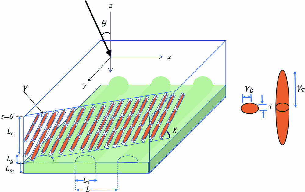
    A schematic of the boundary-value problem is shown in Fig. 1. The region 0<z<Lc is occupied by a CTF (whether infiltrated with a fluid or not), the region Lc+Lg<z<Lc+Lg+Lm by a metal of relative permittivity εm, and the half-spaces z<0 and z>Lc+Lg+Lm are vacuous. The intermediate region Lc<z<Lc+Lg is occupied by a one-dimensional metallic grating with the CTF inside the troughs of the grating. The xz plane is the grating plane because the grating profile is wholly describable in this plane, and L is the period along the x axis.

    Schematic of the boundary-value problem solved for the surface-plasmonic sensor based on the grating-coupled configuration. The CTF is symbolically represented by a single row of nanocolumns, each of which is modeled as a string of electrically small ellipsoids with semi-axes in the ratio 1:γb:γτ.

    Figure 1.Schematic of the boundary-value problem solved for the surface-plasmonic sensor based on the grating-coupled configuration. The CTF is symbolically represented by a single row of nanocolumns, each of which is modeled as a string of electrically small ellipsoids with semi-axes in the ratio 1:γbτ.

    The as-deposited CTF is made of a material of refractive index ns, and a fluid of refractive index nL is present in the void regions of the CTF. The relative permittivity dyadic of the CTF can be written as[18]ε̲̲CTF=S̲̲z·S̲̲y·(εau^zu^z+εbu^xu^x+εcu^yu^y)·S̲̲y1·S̲̲z1,where the principal relative permittivity scalars εa,b,c depend on ns, nL, and the porosity of the CTF[32]. The dyadic S̲̲y=(u^xu^x+u^zu^z)cosχ+(u^zu^xu^xu^z)sinχ+u^yu^yinvolves χ(0,π/2] as the inclination angle of the nanocolumns of the CTF with respect to the xy plane, and the dyadic S̲̲z=(u^xu^x+u^yu^y)cosγ+(u^yu^xu^xu^y)sinγ+u^zu^zindicates that the morphologically significant plane[31] of the CTF is rotated by an angle γ[0,π] about the z axis with respect to the xz plane.

    The relative permittivity dyadic ε̲̲g(x,z)=ε̲̲g(x±L,z) in the intermediate region Lc<z<Lc+Lg is specified as ε̲̲g(x,z)={εmI̲̲(εmI̲̲ε̲̲CTF)U[Lg+Lczg(x)],x[0,L1),ε̲̲CTF,x(L1,L],z(Lc,Lc+Lg),where L1(0,L], the identity dyadic I̲̲=u^xu^x+u^yu^y+u^zu^z, and the unit step function U(ξ)={1,ξ0,0,ξ<0.Although there is no restriction in the theory on the shape of the corrugations, we chose the grating shape function g(x)=Lgsin(πx/L1),for all numerical results presented here.

    Without loss of generality, the interface z=0 is illuminated by a plane wave propagating at the polar angle θ with respect to the z axis and propagating in the xz plane. Although the incident plane wave can be arbitrarily polarized, we fixed it to be p polarized (i.e., Einc·u^y=0) because that polarization state is commonly used in SPP-wave-based sensors. Since the plane of incidence (i.e., the xz plane) coincides with the grating plane, the electromagnetic field reflected in the half-space z<0 and the electromagnetic field transmitted in the half-space z>Lc+Lg+Lm are independent of y.

    We used the rigorous coupled-wave approach (RCWA)[1,33,34] to calculate the absorptance Ap of the metal-CTF structure as a function of the incidence angle θ of a p-polarized plane wave[19]. In the RCWA, the electric and magnetic field phasors everywhere are expanded as infinite series of Floquet harmonics of both p- and s-polarization states. For the chosen problem, the Floquet harmonics of orders n{0,±1,±2,±3} express the x dependence of the field phasors using exp[ikx(n)x], where kx(n)=k0sinθ+n2π/L.The relative permittivity dyadic is expanded as a Fourier series with respect to x for every z(0,Lc+Lg+Lm) and substituted in the frequency-domain Maxwell curl postulates. The result is an infinite number of coupled ordinary differential equations. These are truncated so that Floquet harmonics of orders |n|>Nt+1, Nt1, are ignored, and a finite number of resulting ordinary differential equations are then solved by applying the piecewise-uniform approximation[1] in the region 0<z<Lc+Lg+Lm. Specular and non-specular reflectances and transmittances of orders n[Nt,Nt] are determined using a stable algorithm, from which the absorptance is obtained by applying the principle of conservation of energy[18,19]. When the thickness Lm significantly exceeds the skin depth[35] in the chosen metal, the transmitted electric and magnetic fields are negligibly small in magnitude. Care must be taken to ensure that convergent results are obtained as Nt is increased from unity.

    3. Numerical Results and Discussion

    3.1. CTF homogenization

    The sensor considered in this paper essentially estimates the change in the refractive index nL of the fluid infiltrating the CTF because of changes in the relative permittivity scalars εa,b,c. These three scalars were numerically estimated using a homogenization formalism. There are several homogenization formalisms, including the Maxwell Garnett formalism[36], the Bragg–Pippard formalism[29], and the Bruggeman formalism[31]. The Bruggeman formalism is more reliable and widely used in optics[37,38] because it treats all constituent materials equally, unlike the other two formalisms. We also used the Bruggeman formalism in this work to estimate εa,b,c as functions of nL[32].

    Made of a material of refractive index ns, each nanocolumn of the CTF was represented as a string of electrically small ellipsoids with semi-axes in the ratio 1:γb:γτ so that their shape is characterized by the dyadic[31]U̲̲=S̲̲z·S̲̲y(u^zu^z+γτu^xu^x+γbu^yu^y)·S̲̲y1·S̲̲z1,with γb in the vicinity of unity and γτ1, as shown in Fig. 1. During the deposition of a CTF, collimated vapor of the evaporated material is incident on a planar substrate at an angle χv(0,π/2] with respect to the substrate plane. This vapor condenses on the substrate in the form of nanocolumns inclined at an angle χχv. We selected the uninfiltrated (i.e., nL=1) CTF to have been made by evaporating tantalum oxide with[39]{εa=[1.1961+1.5439ν0.7719ν2]2εb=[1.4600+1.0400ν0.5200ν2]2εc=[1.3532+1.2296ν0.6148ν2]2χ=arctan(3.1056tanχv),where ν=2χv/π. Adopting the inverse Bruggeman formalism devised for CTFs[32], we set γτ=15 and computed the parameters ns, f, and γb as functions of χv using Eq. (9).

    In order to numerically explore the grating-coupled excitation of SPP waves for sensing, we fixed χv=15deg; hence, χ=39.77deg. Furthermore, the inverse Bruggeman formalism yielded ns=2.2999, f=0.4439, and γb=2.4322 for χv=15deg. These data were then employed in the forward Bruggeman formalism[32] to find εa,b,c as functions of nL>1.

    3.2. Canonical boundary-value problem

    As mentioned previously, the basic principle of a surface-plasmonic sensor is sensing the change in the incidence angle θ, where an SPP wave is excited when the refractive index nL of the infiltrating fluid changes. The excitation of the SPP wave can be best inferred by identifying those peaks in the angular spectrum of Ap that do not change location on the θ axis when the thickness of the partnering dielectric material is changed above a threshold value[40], since SPP waves are localized to their interface. The angular locations of the thickness-independent absorptance peaks must be matched against the SPP waves that are solutions of the underlying canonical boundary-value problem[26,41]. In this canonical problem, only a single interface between the two partnering materials occupying half-spaces is present to rule out the excitation of waveguide modes[16,42]. Therefore, we present the solution of the underlying canonical problem before the data calculated for the grating-coupled surface-plasmonic sensor.

    In this canonical problem, one half-space is occupied by the fluid-infiltrated CTF, whereas a metal occupies the other half-space[43]. Let the SPP wave propagate in the interface plane parallel to the unit vector u^x. The electric and magnetic field phasors vary spatially as exp[i(qx+αz)], with Im(α)<0 in the fluid-infiltrated CTF and Im(α)>0 in the metal so that the field phasors decay as |z|. The complex-valued wavenumber q yields the phase speed and attenuation rate in the direction of propagation. A combination of search and Newton–Raphson methods[44,45] was employed to solve the dispersion equation for SPP waves in order to determine the corresponding values of q. We assumed the metal as silver with relative permittivity εm=15.4+0.4i[46] and that the CTF is made by evaporating tantalum oxide[39]; furthermore, γ=30deg and λ0=633nm.

    Only one solution of the dispersion equation was found for any value of nL. Thus, only one SPP wave propagating along the x axis can be excited, although it can have multiple excitations in the grating-coupled configuration[18,19].

    The real and imaginary parts of the relative wavenumber q/k0 of the SPP wave propagating along the x axis are presented in Figs. 2(a) and 2(b), respectively, as functions of the refractive index nL. These plots show an approximately linear relationship between q and nL, which is desirable for a good sensor.

    (a) Real and (b) imaginary parts of q/k0 of the SPP wave propagating along the x axis as functions of the refractive index nL of the infiltrating fluid computed using solutions of the canonical boundary-value problem, whereas χv = 15 deg, γ = 30 deg, and εm = −15.4 + 0.4i, see Sections 3.1 and 3.2 for other relevant parameters.

    Figure 2.(a) Real and (b) imaginary parts of q/k0 of the SPP wave propagating along the x axis as functions of the refractive index nL of the infiltrating fluid computed using solutions of the canonical boundary-value problem, whereas χv = 15 deg, γ = 30 deg, and εm = −15.4 + 0.4i, see Sections 3.1 and 3.2 for other relevant parameters.

    3.3. Grating-coupled surface-plasmonic sensor

    To delineate the excitation of the SPP wave in the grating-coupled surface-plasmonic sensor as a function of the fluid refractive index nL, we computed the absorptance Ap as a function of the incidence angle θ using the RCWA. We fixed Nt=15 after checking that Ap converged within a tolerance limit of ±0.1%. As in Sections 3.1 and 3.2, we fixed λ0=633nm, χv=15deg, γ=30deg, εm=15.4+0.4i, and γτ=15. Furthermore, we fixed L1=0.5L, Lm=30nm, and Lg=20nm, but Lc was kept variable between 1000 and 4000 nm.

    The plots in Fig. 3 present Ap as a function of θ for Lc{1000,2000,3000,4000}nm and nL{1,1.27,1.37,1.43,1.70} when L=500nm. Either one, two, or three absorptance peaks are present in each angular spectrum. The absorptance peaks with thickness-independent locations on the θ axis were correlated with the data available in Fig. 2. For this correlation, we decided that |1kx(n)/Re(q)|0.05 for some n[Nt,Nt] at an absorptance peak attributed to the excitation of an SPP wave as a Floquet harmonic of order n[19].

    Absorptance Ap as a function of incidence angle θ for Lc∈{1000, 2000, 3000, 4000} nm and L = 500 nm in the grating-coupled configuration. Whereas (a) nL = 1, (b) nL = 1.27, (c) nL = 1.37, (d) nL = 1.43, and (e), (f) nL = 1.70, see Sections 3.1 and 3.3 for other relevant parameters. A downward arrow identifies the excitation of the SPP wave as a Floquet harmonic of order n, which is indicated alongside the arrow.

    Figure 3.Absorptance Ap as a function of incidence angle θ for Lc∈{1000, 2000, 3000, 4000} nm and L = 500 nm in the grating-coupled configuration. Whereas (a) nL = 1, (b) nL = 1.27, (c) nL = 1.37, (d) nL = 1.43, and (e), (f) nL = 1.70, see Sections 3.1 and 3.3 for other relevant parameters. A downward arrow identifies the excitation of the SPP wave as a Floquet harmonic of order n, which is indicated alongside the arrow.

    When nL=1 (i.e., air infiltrates the CTF), Fig. 3(a) shows that the SPP wave with q=(1.6561+0.0037i)k0 is excited at θp24.4deg because of the in-plane wavenumber kx(1)=1.7131k0 of the Floquet harmonic of order n=+1 andθp62.6deg because of the in-plane wavenumber kx(2)=1.7122k0 of the Floquet harmonic of order n=2

    which match Re(q) well according to the 5%-criterion adopted by us. This double excitation of the SPP wave is advantageous for reliable sensing, with a schema relying on artificial neural networks[47].

    The absorptance spectra in Fig. 3(b) illustrate the excitation of an SPP wave for nL=1.27 at θp40.5deg, when the in-plane wavenumber kx(1)=1.9494k0 of the Floquet harmonic of order n=+1 matches the solution of the canonical problem with q=(1.8753+0.0056i)k0. There is no evidence for the second excitation of the SPP wave for nL=1.27.

    However, Fig. 3(c) again shows that the excitation of the SPP wave is possible for two values of the incidence angle as two different Floquet harmonics for nL=1.37. The first excitation occurs at θp34.6deg, when the in-plane wavenumber kx(2)=2.0322k0 of the Floquet harmonic of order n=2 matches the canonical solution with q=(1.9618+0.0064i)k0. The second excitation occurs at θp46.7deg, when kx(1)=2.0278k0 of the Floquet harmonic of order n=+1 is a good match. When nL=1.43, the absorptance spectra in Fig. 3(d) demonstrate that the SPP wave with q=(2.0142+0.0069i)k0 is excited at θp30.1deg because of the in-plane wavenumber kx(2)=2.0985k0 of the Floquet harmonic of order n=2 andθp52.6deg because of the in-plane wavenumber kx(1)=2.0944k0 of the Floquet harmonic of order n=+1

    which match Re(q) reasonably well.

    Finally, when nL=1.70, Figs. 3(e) and 3(f) demonstrate that the SPP wave with q=(2.2555+0.0097i)k0 is excited at θp16.5deg because of the in-plane wavenumber kx(2)=2.3160k0 of the Floquet harmonic of order n=2,θp22.9deg because of the in-plane wavenumber kx(2)=2.2109k0 of the Floquet harmonic of order n=2, andθp65.7deg because of the in-plane wavenumber kx(1)=2.2114k0 of the Floquet harmonic of order n=+1

    which match Re(q) reasonably well. Contained in this triple excitation of the SPP wave is a doublet: the same SPP wave is excited at two different values of θ but as the same Floquet harmonic (n=2 when nL=1.70). We have observed that the excitation at one angle of incidence is less efficient than at the other in a doublet. In Fig. 3(e), the doublet appears at θp16.5deg and θp22.9deg with higher Ap and, therefore, stronger excitation at θp16.5deg than at θp22.9deg. Evidence of the doublet in the grating-coupled configuration has already been reported[18]. The triple excitation of the SPP wave is going to be even more advantageous for reliable sensing than double excitation, in a schema relying on artificial neural networks[47].

    The results of Fig. 3 allow us to conclude that, as θ is varied, the SPP wave can be multiply excited, depending upon the value of the refractive index nL of the infiltrating fluid. In order to examine the effect of nL in detail, Fig. 4 shows the angular spectra of Ap when Lc=3000nm and L=500nm for diverse values of nL; all other parameters are the same as that mentioned at the beginning of Section 3.3.

    Absorptance Ap as a function of incidence angle θ when (a) nL ∈ [1.00, 1.20], (b) nL ∈ [1.21, 1.29], (c) nL ∈ [1.30, 1.39], and (d) nL ∈ [1.40, 1.50]. Whereas Lc = 3000 nm and L = 500 nm, see Sections 3.1 and 3.3 for other relevant parameters. The horizontal arrows show the direction of the shift of peaks representing the excitation of the SPP wave.

    Figure 4.Absorptance Ap as a function of incidence angle θ when (a) nL ∈ [1.00, 1.20], (b) nL ∈ [1.21, 1.29], (c) nL ∈ [1.30, 1.39], and (d) nL ∈ [1.40, 1.50]. Whereas Lc = 3000 nm and L = 500 nm, see Sections 3.1 and 3.3 for other relevant parameters. The horizontal arrows show the direction of the shift of peaks representing the excitation of the SPP wave.

    Figure 4(a) contains two absorptance peaks indicating SPP-wave excitation when nL[1.00,1.20]. For each nL, one peak is for n=+1 when kx(1)Re(q), and the other peak is for n=2 when kx(2)Re(q), where q is the wavenumber of the possible SPP wave gleaned from Fig. 2. Figure 4(b) has a solitary absorptance peak signifying the excitation of the SPP wave as a Floquet harmonic of order n=+1 when nL[1.21,1.29]. A similar absorptance peak for n=2 is absent, and we found that double excitation of the SPP wave is not possible for nL[1.21,1.29]. When nL=1.30, the absorptance peak for n=+1 is not present in Fig. 4(c). Two absorptance peaks for each value of nL appear again in Figs. 4(c) and 4(d) when nL[1.33,1.50]: one peak for n=+1 when kx(1)Re(q) and the second peak for n=2 when kx(2)Re(q). The shifts in the angular locations of the two absorptance peaks indicate that these peaks begin far apart from each other from small values of nL and come closer as nL increases. At intermediate values of nL, the peaks merge, and only one peak is observed. When nL increases further, the single peak divides into two peaks that get farther apart when nL is increased further.

    To analyze the usefulness of the peaks for optical sensing, we computed the sensitivity as S=ΔθpΔnL,where θp is the nL-dependent angular location of an absorptance peak, and Δθp is the change in θp when the refractive index of the infiltrating fluid changes by ΔnL. The sensitivity was computed from the absorptance plots for the excitation of the SPP wave as a Floquet harmonic of order n{2,1} and is presented in Fig. 5 as a function of nL for Lc=3000nm and L=500nm. Additionally, S was computed from the canonical problem by solving Re(q)=k0sinθp+2nπ/L for θp as a function of nL and then using Eq. (10).

    Sensitivity S as a function of the refractive index nL of the infiltrating fluid. The sensitivity, given by Eq. (10), was computed from the absorptance plots like the ones given in Fig. 4 with Lc = 3000 nm and L = 500 nm. Doublet excitation is possible for some ranges of nL in Fig. 5(c). The predicted sensitivity was computed using the solutions of the canonical problem in Re(q) = k0 sin θp + 2nπ/L to find predicted θp as a function of nL. All parameters were kept the same as for Fig. 4.

    Figure 5.Sensitivity S as a function of the refractive index nL of the infiltrating fluid. The sensitivity, given by Eq. (10), was computed from the absorptance plots like the ones given in Fig. 4 with Lc = 3000 nm and L = 500 nm. Doublet excitation is possible for some ranges of nL in Fig. 5(c). The predicted sensitivity was computed using the solutions of the canonical problem in Re(q) = k0 sin θp + 2nπ/L to find predicted θp as a function of nL. All parameters were kept the same as for Fig. 4.

    The predicted sensitivity and the sensitivity computed from the absorptance spectra are in good agreement. From Fig. 5, we observe that the sensitivities of the absorptance peaks corresponding to n=+1 are higher than those of the absorptance peaks corresponding to n=2.

    So far, we have presented the results in an analytical sense that tell us the angular location θp of an absorptance peak (that indicates the excitation of an SPP wave) when we know nL. However, in practice, we have to accomplish the reverse task, i.e., find the value of nL from the knowledge of the angular location of the peak absorptance. To make this easier, Fig. 6 shows θp as a function of nL for both types of absorptance peaks in Fig. 4. Once the angular spectrum of absorptance has been measured for an unknown fluid, we can find the angular locations of the absorptance peaks and use those locations to find nL from Fig. 6. The requirement of matching two values of θp (for many values of nL) with one value of nL makes the measurement of the refractive index more reliable than the case when only one absorptance peak is present.

    The angular location θp of an absorptance peak indicating the excitation of the SPP wave as a function of the refractive index nL ∈ [0.3, 2.5] of the infiltrating fluid. All parameters are the same as for Fig. 4. Triple excitation of the SPP wave occurs in the blue-shaded regions, double excitation in the gray-shaded regions, and single excitation in the green-shaded regions.

    Figure 6.The angular location θp of an absorptance peak indicating the excitation of the SPP wave as a function of the refractive index nL ∈ [0.3, 2.5] of the infiltrating fluid. All parameters are the same as for Fig. 4. Triple excitation of the SPP wave occurs in the blue-shaded regions, double excitation in the gray-shaded regions, and single excitation in the green-shaded regions.

    There is only one absorptance peak indicating SPP-wave excitation for nL[1.21,1.31][1.92,2.21], two such absorptance peaks for nL[0.3,1.20][1.32,1.60][1.68,1.69][1.75,1.91], and three absorptance peaks for nL[1.61,1.67][1.70,1.74]. When three absorptance peaks are possible, two of those peaks form a doublet because both of those peaks satisfy the 5% criterion for the same n[18]. The doublet exists for n=+1 when nL[1.61,1.67] and for n=2 when nL[1.70,1.74].

    The nL-ranges for single, double, and triple excitation of the SPP wave depend upon the value of the grating period L. Thus, for L=600nm, we determined that single excitation occurs for nL[1.30,1.31][1.92,2.45], double excitation for nL[0.3,1.29][1.46,1.91], and triple excitation for nL[1.32,1.45]. Likewise, for L=700nm, single excitation occurs for nL=1.33, double excitation for nL[1.30,1.32][1.95,2.50], and triple excitation for nL[0.3,1.29][1.90,1.94]. Therefore, L should be chosen to obtain double or triple excitation for the suspected range of nL for a certain fluid.

    Figure 6 indicates that multiple excitations can result in ambiguity when determining nL. For instance, if θp27deg and θp58deg are found for a sample, then both nL=1.05 and nL=1.50 are possible according to Fig. 6. The ambiguity can be eliminated by repeating the experiment after diluting the sample. Another way to eliminate the ambiguity is by incorporating Ap-versus-θ data for a wide enough θ range in a schema comprising an artificial neural network[47]. Yet another way may be to use two or more sensors with different values of the grating period L.

    Before concluding this section, we must address two issues. First, the air/CTF/metal structure can function as an open-face waveguide[42,48,49], whose modes can also be used for sensing an infiltrant fluid. However, as the propagation characteristics of a waveguide mode will depend strongly on the CTF thickness Lc, the angular location of an absorptance peak due to the excitation of that waveguide mode will be highly susceptible to a change in Lc. In contrast, the angular location of an absorptance peak due to the excitation of an SPP wave guided by the metal/CTF interface is weakly dependent on Lc (beyond a threshold value)[28], which confers the advantage of reliability against manufacturing variabilities. Second, although the air/CTF interface could guide surface waves[1], we were unable to find any pertinent solutions of the relevant canonical boundary-value problem[50,51] for the chosen CTF, whether infiltrated or not.

    4. Concluding Remarks

    An optical sensor was theoretically analyzed for the plane-wave illumination of a CTF on top of a one-dimensional metallic surface-relief grating. The incident plane wave was taken to be p polarized, and the plane of incidence coincided with the grating plane but not necessarily with the morphologically significant plane of the CTF. The absorptance was computed as a function of the angle of incidence for different thicknesses of the CTF, using the RCWA. The thickness-independent absorptance peaks were identified, and the in-plane wavenumbers of the possible Floquet harmonics were compared with the wavenumber of the SPP wave predicted by the associated canonical boundary-value problem. The change in the angular location of the absorptance peak representing SPP-wave excitation as a function of the refractive index of the fluid infiltrating the CTF was determine to find the sensitivity.

    Double and triple excitations of the same SPP wave were found to be possible, depending on the refractive index of the fluid, which can help increase the reliability of results by sensing the same fluid with more than one excitation of the SPP wave, possibly with a schema that incorporates artificial neural networks. In multiple excitations, the same SPP wave is excited as Floquet harmonics of various orders. It is even possible that the excitation occurs at different angles of incidence but as the Floquet harmonic of the same order; however, all excitations are not going to be equally efficient. The theoretical sensitivity reported here can be as high as 230 deg/RIU, which shows that higher sensitivity can be achieved using the grating-coupled configuration than a prism-coupled configuration[27,28,52].

    References

    [1] J. A. Polo, T. G. Mackay, A. Lakhtakia. Electromagnetic Surface Waves: A Modern Perspective(2013).

    [2] S. A. Maier. Plasmonics: Fundamentals and Applications(2007).

    [3] J. Homola. Surface Plasmon Resonance Based Sensors(2006).

    [4] Y. Tang, X. Zeng. Surface plasmon resonance: an introduction to a surface spectroscopy technique. J. Chem. Edu., 87, 742(2010).

    [5] G. Flätgen, K. Krischer, G. Ertl. Spatio-temporal pattern formation during the reduction of peroxodisulfate in the bistable and oscillatory regime: a surface plasmon microscopy study. J. Electroanal. Chem., 409, 183(1996).

    [6] A. W. Peterson, M. Halter, A. Tona, A. L. Plant. High resolution surface plasmon resonance imaging for single cells. BMC Cell Biol., 15, 35(2014).

    [7] J. S. Sekhon, S. Verma. Plasmonics: the future wave of communication. Curr. Sci., 101, 484(2011).

    [8] R. Agrahari, A. Lakhtakia, P. K. Jain. Information transfer by near-infrared surface-plasmon-polariton waves on silver/silicon interfaces. Sci. Rep., 9, 12095(2019).

    [9] I. Abdulhalim, M. Zourob, A. Lakhtakia. Surface plasmon resonance for biosensing: a mini-review. Electromagnetics, 28, 214(2008).

    [10] A. M. Shrivastav, U. Cvelbar, I. Abdulhalim. “A comprehensive review on plasmonic-based biosensors used in viral diagnostics. Commun. Biol., 4, 70(2021).

    [11] R. H. Ritchie. Plasma losses by fast electrons in thin films. Phys. Rev., 106, 874(1957).

    [12] T. Turbadar. Complete absorption of light by thin metal films. Proc. Phys. Soc., 73, 40(1959).

    [13] E. Kretschmann, H. Raether. Radiative decay of nonradiative surface plasmons excited by light. Z. Naturforsch., 23, 2135(1968).

    [14] A. Otto. Excitation of nonradiative surface plasma waves in silver by the method of frustrated total reflection. Z. Phys., 216, 398(1968).

    [15] G. I. Stegeman, R. F. Wallis, A. A. Maradudin. Excitation of surface polaritons by end-fire coupling. Opt. Lett., 8, 386(1983).

    [16] L. Liu, M. Faryad, A. S. Hall, G. D. Barber, S. Erten, T. E. Mallouk, A. Lakhtakia, T. S. Mayer. Experimental excitation of multiple surface-plasmon-polariton waves and waveguide modes in a one-dimensional photonic crystal atop a two-dimensional metal grating. J. Nanophoton., 9, 093593(2015).

    [17] G. Ruffato, F. Romanato. Grating-coupled surface plasmon resonance in conical mounting with polarization modulation. Opt. Lett., 37, 2718(2012).

    [18] F. Chiadini, V. Fiumara, A. Scaglione, A. Lakhtakia. Multiple excitations of a surface-plasmon-polariton wave guided by a columnar thin film deposited on a metal grating. Opt. Eng., 53, 127105(2014).

    [19] K. Mujeeb, M. Faryad, J. V. Urbina, A. Lakhtakia. Effect of orientation on excitation of surface-plasmon-polariton waves guided by a columnar thin film deposited on a metal grating. Opt. Eng., 59, 069801(2020).

    [20] J. Dostálek, J. Homola, M. Miler. Rich information format surface plasmon resonance biosensor based on array of diffraction gratings. Sens. Actuat. B: Chem., 107, 154(2005).

    [21] D. W. Unfricht, S. L. Colpitts, S. M. Fernandez, M. A. Lynes. Grating-coupled surface plasmon resonance: a cell and protein microarray platform. Proteomics, 5, 4432(2005).

    [22] F.-C. Chien, C.-Y. Lin, J.-N. Yih, K.-L. Lee, C.-W. Chang, P.-K. Wei, C.-C. Sun, S.-J. Chen. Coupled waveguide–surface plasmon resonance biosensor with subwavelength grating. Biosens. Bioelectron., 22, 2737(2007).

    [23] C. Thirstrup, W. Zong, M. Borre, H. Neff, H. C. Pedersen, G. Holzhueter. Diffractive optical coupling element for surface plasmon resonance sensors. Sens. Actuat. B: Chem., 100, 298(2004).

    [24] P. Adam, J. Dostálek, J. Homola. Multiple surface plasmon spectroscopy for study of biomolecular systems. Sens. Actuat. B: Chem., 113, 774(2006).

    [25] S. J. Elston, J. R. Sambles. Surface plasmon-polaritons on an anisotropic substrate. J. Mod. Opt., 37, 1895(1990).

    [26] M. Faryad, J. A. Polo, A. Lakhtakia. Multiple trains of same-color surface plasmon-polaritons guided by the planar interface of a metal and a sculptured nematic thin film. Part IV: canonical problem. J. Nanophoton., 4, 043505(2010).

    [27] S. S. Jamaian, T. G. Mackay. On columnar thin films as platforms for surface-plasmonic-polaritonic optical sensing: higher-order considerations. Opt. Commun., 285, 5535(2012).

    [28] S. E. Swiontek, M. Faryad, A. Lakhtakia. Surface plasmonic polaritonic sensor using a dielectric columnar thin film. J. Nanophoton., 8, 083986(2014).

    [29] I. J. Hodgkinson, Q. h. Wu. Birefringent Thin Films and Polarizing Elements(1998).

    [30] D. M. Mattox. The Foundations of Vacuum Coating Technology(2003).

    [31] A. Lakhtakia, R. Messier. Sculptured Thin Films: Nanoengineered Morphology and Optics(2005).

    [32] T. G. Mackay, A. Lakhtakia. Determination of constitutive and morphological parameters of columnar thin films by inverse homogenization. J. Nanophoton., 4, 040201(2010).

    [33] M. G. Moharam, T. K. Gaylord. Rigorous coupled-wave analysis of metallic surface-relief gratings. J. Opt. Soc. Am. A, 3, 1780(1986).

    [34] M. G. Moharam, E. B. Grann, D. A. Pommet, T. K. Gaylord. Formulation for stable and efficient implementation of the rigorous coupled-wave analysis of binary gratings. J. Opt. Soc. Am. A, 12, 1068(1995).

    [35] M. F. Iskander. Electromagnetic Fields and Waves(2013).

    [36] L. Ward. The Optical Constants of Bulk Materials and Films(2000).

    [37] A. Lakhtakia. Selected Papers on Linear Optical Composite Materials(1996).

    [38] T. G. Mackay, A. Lakhtakia. Modern Analytical Electromagnetic Homogenization with Mathematica®(2020).

    [39] I. Hodgkinson, Q. H. Wu, J. Hazel. Empirical equations for the principal refractive indices and column angle of obliquely deposited films of tantalum oxide, titanium oxide, and zirconium oxide. Appl. Opt., 37, 2653(1998).

    [40] M. A. Motyka, A. Lakhtakia. Multiple trains of same-color surface plasmon-polaritons guided by the planar interface of a metal and a sculptured nematic thin film. J. Nanophoton., 2, 021910(2008).

    [41] T. G. Mackay. On the identification of surface waves in numerical studies. Plasmonics, 14, 1(2019).

    [42] T. Khaleque, R. Magnusson. Light management through guided-mode resonances in thin-film silicon solar cells. J. Nanophoton., 8, 083995(2014).

    [43] J. A. Polo, S. R. Nelatury, A. Lakhtakia. Propagation of surface waves at the planar interface of a columnar thin film and an isotropic substrate. J. Nanophoton., 1, 013501(2007).

    [44] V. L. Zaguskin. Handbook of Numerical Methods for the Solution of Algebraic and Transcendental Equations(1961).

    [45] Y. Jaluria. Computer Methods for Engineering(1996).

    [46] F. Hao, P. Nordlander. Efficient dielectric function for FDTD simulation of the optical properties of silver and gold nanoparticles. Chem. Phys. Lett., 446, 115(2007).

    [47] P. D. McAtee, S. T. S. Bukkapatnam, A. Lakhtakia. Artificial neural network to estimate the refractive index of a liquid infiltrating a chiral sculptured thin film. J. Nanophoton., 13, 046006(2019).

    [48] A. W. Snyder, J. D. Love. Optical Waveguide Theory(1983).

    [49] L. Liu, M. Faryad, A. S. Hall, G. D. Barber, S. Erten, T. E. Mallouk, A. Lakhtakia, T. S. Mayer. Experimental excitation of multiple surface-plasmon-polariton waves and waveguide modes in a one-dimensional photonic crystal atop a two-dimensional metal grating. J. Nanophoton., 9, 093593(2015).

    [50] A. N. Furs, V. M. Galynsky, L. M. Barkovsky. Surface polaritons in symmetry planes of biaxial crystals. J. Phys. A: Math. Gen., 38, 8083(2005).

    [51] J. A. Polo, S. R. Nelatury, A. Lakhtakia. Propagation of surface waves at the planar interface of a columnar thin film and an isotropic substrate. J. Nanophoton., 1, 013501(2007).

    [52] T. G. Mackay, A. Lakhtakia. Modeling columnar thin films as platforms for surface-plasmonic-polaritonic optical sensing. Photon. Nanostruct.: Fundam. Appl., 8, 140(2010).

    Kiran Mujeeb, Muhammad Faryad, Akhlesh Lakhtakia, Julio V. Urbina. Surface-plasmonic sensor using a columnar thin film in the grating-coupled configuration [Invited][J]. Chinese Optics Letters, 2021, 19(8): 083601
    Download Citation