• Photonics Research
  • Vol. 9, Issue 6, 1013 (2021)
Chunlei Sun1、2, Chuyu Zhong3、4, Maoliang Wei3、4, Hui Ma3、4, Ye Luo1、2, Zequn Chen1、2, Renjie Tang1、2, Jialing Jian1、2, Hongtao Lin3、4, and Lan Li1、2、*
Author Affiliations
  • 1Key Laboratory of 3D Micro/Nano Fabrication and Characterization of Zhejiang Province, School of Engineering, Westlake University, Hangzhou 310024, China
  • 2Institute of Advanced Technology, Westlake Institute for Advanced Study, Hangzhou 310024, China
  • 3Key Laboratory of Micro-Nano Electronics and Smart System of Zhejiang Province, College of Information Science and Electronic Engineering, Zhejiang University, Hangzhou 310027, China
  • 4School of Microelectronics, Zhejiang University, Hangzhou 310027, China
  • show less
    DOI: 10.1364/PRJ.420005 Cite this Article Set citation alerts
    Chunlei Sun, Chuyu Zhong, Maoliang Wei, Hui Ma, Ye Luo, Zequn Chen, Renjie Tang, Jialing Jian, Hongtao Lin, Lan Li. Free-spectral-range-free filters with ultrawide tunability across the S + C + L band[J]. Photonics Research, 2021, 9(6): 1013 Copy Citation Text show less
    (a) Schematic of our proposed filter with a grating-assisted F-P cavity selectively trapping a single narrowband beam in the ultrawide waveband range. (b) Some key parts of the filter as well as the design parameters. (c) Typical spectral response of a Bragg grating (dashed blue curve) and F-P cavity with ideal mirrors (solid red curve). When the stopband of the Bragg grating is smaller than the FSR of the F-P cavity, Δλsb<FSRFP, there remains only one major resonance.
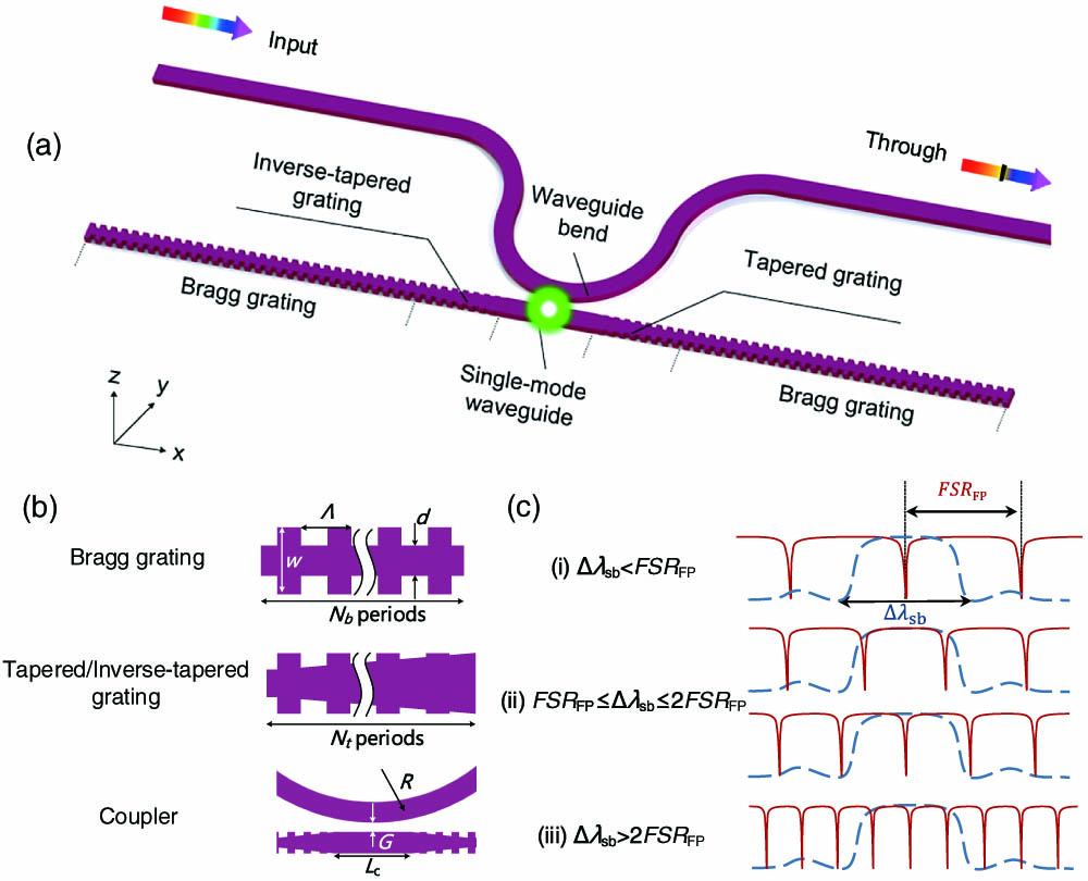
    Fig. 1. (a) Schematic of our proposed filter with a grating-assisted F-P cavity selectively trapping a single narrowband beam in the ultrawide waveband range. (b) Some key parts of the filter as well as the design parameters. (c) Typical spectral response of a Bragg grating (dashed blue curve) and F-P cavity with ideal mirrors (solid red curve). When the stopband of the Bragg grating is smaller than the FSR of the F-P cavity, Δλsb<FSRFP, there remains only one major resonance.
    (a) Calculated central wavelength λc of the Bragg grating and stopband Δλsb for d=240, 260, 280, 300, 320, 340, and 360 nm. (b) Calculated FSR of the F-P cavity FSRFP and (c) Δλsb/FSRFP ratio for different central waveguide lengths (Lc=0–30 μm) and central transom widths (d=240, 300, 360 nm). The figure is divided into three regions filled with different colors and labeled by (i)–(iii). (d) Calculated spectral responses of the filter for Lc=0, 4, 6, and 20 μm, corresponding to cases (i)–(iii).
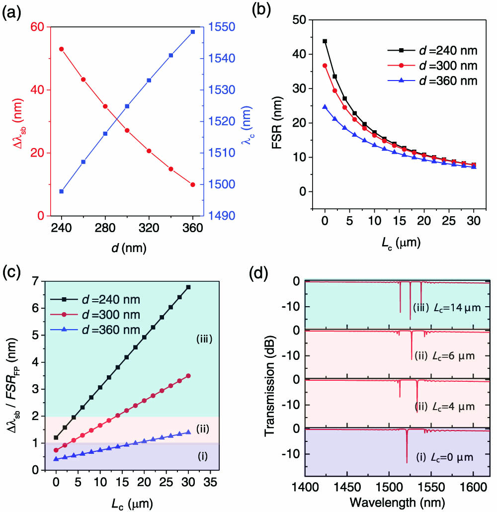
    Fig. 2. (a) Calculated central wavelength λc of the Bragg grating and stopband Δλsb for d=240, 260, 280, 300, 320, 340, and 360 nm. (b) Calculated FSR of the F-P cavity FSRFP and (c) Δλsb/FSRFP ratio for different central waveguide lengths (Lc=030  μm) and central transom widths (d=240, 300, 360 nm). The figure is divided into three regions filled with different colors and labeled by (i)–(iii). (d) Calculated spectral responses of the filter for Lc=0, 4, 6, and 20 μm, corresponding to cases (i)–(iii).
    (a) Calculated transmission of the filter in the wavelength range of 1400–1620 nm. (b) Simulated electric field distribution at the wavelengths of 1400, 1521, 1522, and 1620 nm. The white arrow shows the direction of the injected light.
    Fig. 3. (a) Calculated transmission of the filter in the wavelength range of 1400–1620 nm. (b) Simulated electric field distribution at the wavelengths of 1400, 1521, 1522, and 1620 nm. The white arrow shows the direction of the injected light.
    SEM image of the fabricated filter as well as the insets illustrating the zoom-in views of Bragg gratings and the central coupling region.
    Fig. 4. SEM image of the fabricated filter as well as the insets illustrating the zoom-in views of Bragg gratings and the central coupling region.
    (a) Measured transmission spectrum of the fabricated device. The inset shows the spectral response around the resonant wavelength. (b) Measured transmission spectra of the fabricated devices with various pitches.
    Fig. 5. (a) Measured transmission spectrum of the fabricated device. The inset shows the spectral response around the resonant wavelength. (b) Measured transmission spectra of the fabricated devices with various pitches.
    Measured transmission responses of the filter (a) covered under liquids with various refractive indices, and (b) heated by increasing temperature. The insets in (a) and (b) show linear fits of the resonant wavelength shifts versus refractive index and temperature, respectively. (c) Measured transmission response of the device consisting of five FSR-free filters with different pitches cascaded in series. The inset shows the optical microscope view of the multichannel filter.
    Fig. 6. Measured transmission responses of the filter (a) covered under liquids with various refractive indices, and (b) heated by increasing temperature. The insets in (a) and (b) show linear fits of the resonant wavelength shifts versus refractive index and temperature, respectively. (c) Measured transmission response of the device consisting of five FSR-free filters with different pitches cascaded in series. The inset shows the optical microscope view of the multichannel filter.
    Chunlei Sun, Chuyu Zhong, Maoliang Wei, Hui Ma, Ye Luo, Zequn Chen, Renjie Tang, Jialing Jian, Hongtao Lin, Lan Li. Free-spectral-range-free filters with ultrawide tunability across the S + C + L band[J]. Photonics Research, 2021, 9(6): 1013
    Download Citation