Key Laboratory of Optical System Advanced Manufacturing Technology, Changchun Institute of Optics, Fine Mechanics, and Physics, Chinese Academy of Sciences, Changchun 130033, China
Feng Yan. Cooperative testing of an optical system of an assembled space telescope[J]. Chinese Optics Letters, 2015, 13(Suppl.): S22204
Copy Citation Text
A new method developed for wavefront error (WFE) testing of an assembled space telescope is described in this Letter. The main idea of this method is to image a small bright target on the focal plane array assembly by the space telescope itself; the imaging light beams can be reflected to the focal plane array by a plane mirror in front of the aperture of the system under test and two images (one is in-focus and the other is defocused) can be obtained. The WFE of the optical system can be calculated with a phase diversity algorithm according to two images of the target on the focal plane array assembly. The residual error and limitations of this method are discussed and a simulation result is shown, which shows the application potential of this technology.
A collimator is always used to test the image quality of a space telescope after the focal plane array (FPA) is fixed. Nevertheless, as the aperture size and focal length of these systems become increasingly large, it will be more difficult to test the image quality of these systems considering that the increasing difficulties of fabricating and transferring large-aperture and long focal length collimators[1–8]. Moreover, it is also very difficult to maintain an appropriate environment condition for optical testing, especially in the field. In this Letter, a new method for testing large assembled space telescopes is proposed. A bright small target is appended on the FPA assembly. The light beams emitted from the small target pass through the optical system reversely and become parallel at the aperture. Then the parallel light beams are reflected by a plane mirror of proper size, pass through the system again, and finally generate the image of the target. Two images, both in-focus and defocused, can be obtained by moving the FPA. The wavefront error (WFE) can be fitted by phase diversity (PD) algorithm based on the two in-focus and defocused images[9–11]. With this method a collimator of large aperture and long focal length is not needed anymore in the testing of large assembled space telescopes and other large optics. The details of this technology will be presented next.
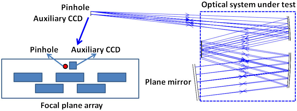
The essential setup of this testing technology is shown in Fig. 1. A lighted pinhole, which is used as the small bright target, is integrated on the component of the FPA and the cone angle of the emitted light from the pinhole is set equal to common convergent light beams to the FPA. The size of the pinhole should be carefully selected such that it can be regarded as a point target and the diffraction effect does not dominate. The emitted plane of the pinhole should be assembled in the same plane of the photosensitive surface of the imaging sensor strictly. A small auxiliary CCD is located as near as possible to the pinhole for self-calibration purposes. Both the pinhole and the small auxiliary CCD should be located within the available field range of the system. A plane mirror should be set just in front of the aperture of the telescope under test.
There are two procedures in the testing process: the first is called self-calibration and the second is called relative testing. The self-calibration procedure is used to establish a reference for testing. The light beams from the pinhole (emit from the pinhole and transmit to the plane mirror in Fig. 1) propagate into the optical system from the imaging space to object space and become parallel when leaving the system at the aperture. The plane mirror of proper size, which should be somewhat larger than the section of parallel light beam, is located just in front of the aperture to reflect the parallel beam back into the system. The interval between the plane mirror and the aperture of optical system should be set as small as possible to remove the effect of airflow as much as possible. The reflected beams pass through the optical system as usual imaging beams and then can be focused on the FPA by adjusting the azimuth and pitching of the plane mirror. Therefore the image of the pinhole can be obtained.
Sign up for Chinese Optics Letters TOC. Get the latest issue of Chinese Optics Letters delivered right to you!Sign up now
Term , the WFE along with the image of the pinhole can be calculated through the PD technique[4–8]. The PD technique needs to collect two images while the first image is in focus containing the unknown WFE of the system, and the second image is diversity image which has an additional aberration. The additional aberration is specially designed and usually considered to be realized as defocusing. The defocus image of the pinhole can be obtained by moving the FPA with a refocusing mechanism.
It is obvious that the light beams emitting from the pinhole pass through the system twice, but follow different paths. Thus the WFE can be divided into two parts where stands for the WFE of the wavefront passing through the system the first time (which propagates from the image space to object space), and stands for the WFE of the wavefront passing through the system the second time (which propagates from the object space to image space). In most cases is different from because of the uncommon paths. The uncommon error depends on the distance between the pinhole and the auxiliary CCD, and the distance between the plane mirror and the aperture of the optical system. A shorter distance corresponds to less uncommon error. The distance between the pinhole and the auxiliary CCD is very small, thus the emitted and reflected light beams share almost the same path such that the effect of the uncommon error is very small. The numerical calculation based on an F/9Cook three-mirror anastigmatic (TMA) system is also performed. When the distance between the pinhole and the auxiliary CCD is set at 20 mm and the distance between the plane mirror and the aperture of the TMA system is set at 1700 mm, the difference introduced by the uncommon error between and is only about with being the light wavelength. Of course the difference varies for different systems, but the value of the difference is in the order of thousandths of for any optical system of space telescopes. Such a difference is actually very small relative to the WFE of system and has little effect on the testing result. Hence it can be regarded approximately that equals without losing accuracy and it can be deduced that Therefore the can be set as the reference of testing.
The second procedure is relative testing. The process is mostly the same as the first procedure. The only difference is the orientation of the plane mirror. The azimuth and the pitching of the plane mirror should be adjusted sucg that the image of the pinhole focuses on the FPA of telescope, not on the auxiliary CCD. In this case , the WFE along with the image of the pinhole can also be divided into two parts as shown in Eq. (1). is the same as self-calibration and has been calculated in the first procedure, while stands for the WFE of a certain field of view (FOV) that is of concern to this work. Once is calibrated, of different FOVs can be obtained by adjusting the orientation of the plane mirror to make the image of the pinhole on the corresponding CCD pixels and subtracting from .
However, there is a disadvantage with this technology in that the aperture of a FOV under test is limited by the overlapping area between the reflected light beams and the normal incident beams of the FOV of concern to this work, as shown in Fig. 2, where the aperture stop of the telescope is supposed to be circular. The intersection area on the first optical surface (from the object space to imaging space) of different light beams is provided in Fig. 2, in which the blue circle denotes the intersection of the emitted light beams, the black circle denotes the intersection of the reflected light beams, and the red circle denotes the intersection of the normal incident light beams of the FOV under test. Obviously it can be observed that although the incident angle of the reflected light beams is the same as the normal incident rays, the transverse position is different from each other. Only the WFE of the FOV in the overlapping area (with black shadow in Fig. 2) can be obtained.
Figure 2.Intersection area on the first optical surface (from object space to imaging space) of different light beams.
The limitation of effective testing area is not all the same for different optical systems. As aforementioned, eliminating the distance between the aperture of the telescope under test and the plane mirror can expand the effective area for testing by cutting the optical paths. Narrow FOV is also propitious to reduce the negative effect of the limitation. Take rug-TMA, system for example; the aperture stop is located at the position of primary mirror and the FOV of such system is always narrow, as shown in Fig. 3(a), such that the plane mirror can be located just in front of the primary mirror so long as keeping a safe interval to the barrel of the telescope. Hence the lost area that cannot be measured is always very small. However, for a cook-TMA system, the stop is located at the position of secondary mirror and the FOV in one direction is usually very wide, as shown in Fig. 3(b), which causes the effective testing area of the widest FOV to be relatively small. The percentage of the effective tested area to the full aperture corresponds to the optical design and mechanical structure of different systems. It can achieve more than 60% even for the widest FOV of most usual telescopes.
A settlement to this problem is to set several pairs of pinholes and small auxiliary CCDs at different locations around the FPA of the telescope under test as shown in Fig. 4. For any given FOV of concern to this work, the nearest pair of point light source and small CCD can be selected to minimize the path difference and maximize the overlapping area. Another settlement is to make the pinhole and the auxiliary CCD move along a trail, which can transfer to the most suitable position for different FOVs under test. Both methods are under preparation and detailed plans will be given in future work. Finally, it must be indicated that the limitation of the testing area is not a fundamental drawback of this method. The main purpose of this testing method is to check if the status of the optical systems changes according to external factors such as temperature, air pressure, mechanical stress, and so on. Only the low spatial-frequency component of WFE will it change against the variation of environmental conditions. The tested area of more than 60% full aperture is enough to detect the change. Detailed analysis is omitted due to the need for brevity.
Figure 4.The FPA setup of the telescope with wild FOV for cooperative testing.
Simulation is performed through the optical design code Zemax and the mathematical program Matlab. Zemax is applied for generating both the infocus and the defocused images of a simulated pinhole and Matlab is used for calculating the WFE by carrying out a PD algorithm. The theoretical WFE of a selected FOV computed by Zemax is set as the reference. A circular area is selected from the overlapping area for convenience of mathematical calculations. The calculated results are shown in Fig. 5, where Fig. 5(a) is and Fig. 5(b) is the WFE of the FOV under test from Zemax as the reference. Only the low spatial-frequency component can be calculated by the PD algorithm, thus only the low spatial-frequency of the WFE from Zemax is provided for comparison.
It can be seen that the reference WFE is and the calculating result is . The difference between them is only . This difference is caused mainly by the uncommon optical paths between the emitted light beams and the reflected light beams as well as other factors. However, the results are still exciting since the difference is very small compared with the real WFE. Practical experiments have also been performed and will be reported in future publications.
The environment factors which may have negative effects on taking images need to be considered when the measurement is carried out in the field. Temperature varies very slowly and has little influence on the result. Air turbulence can cause much difference to the two in-focus and defocused images may introduce incredible error to in the self-calibration process. However, since the testing process cost very little time, the additional error caused by air turbulence can be removed through the comparison of several different groups of results or making an average. The imaging sensor used in this measurement is just the FPA of the space telescope and the entire testing process is highly efficient. Consequently, the stability of the imaging sensor can be ensured in common conditions.
A new technology of measuring space telescope with a large aperture is described in this Letter. The necessary devise for this testing only consists of a pinhole, a small auxiliary CCD around the FPA, and a plane mirror in front of the system aperture, which makes the measurement effective and convenient to perform. Although WFE of a full aperture cannot be tested, the calculated result is useful for performance evaluation, especially in the field.