
Ying CUI, Jun-hua HE, Bing-jing WU, Ya-dong YAN, Rui-hua XU. Design of X-ray Microscope Employing Toroid Mirrors Working at Grazing-incidence[J]. Acta Photonica Sinica, 2019, 48(12): 1211002
- Acta Photonica Sinica
- Vol. 48, Issue 12, 1211002 (2019)
Abstract
0 Introduction
In order to achieve Inertial Confinement Fusion (ICF), high-power laser beams or particle beams are used to irradiate fusion fuels, which are compressed to high temperatures (above 5 000℃) with high density (600 g/cm3). X-ray microscopy which image the X-rays emanating from a laser-produced plasma provides an effective way to diagnose the spatial characteristics of laser plasma, which plays an important role in the study of laser radiation uniformity[
The on-axis aberration of a grazing-incidence spheric-based Kirkpatrick-Baez compound microscope may be precisely corrected. However, for finite fields, the off-axis performance degrades too rapidly for high-spatial-resolution imaging of even the smallest objects of interest[
1 Design of the microscope
The principle of this imaging system combines the characteristics of the KB mirrors and the Wolter microscope. In order to be compact and correct aberrations, toroid mirrors are used instead of two orthogonal cylindrical mirrors in the system. The toroid shapes also present some advantages of brightness compared to KB cylindrical mirrors because only a single toroid mirror can be used to achieve two-dimensional focusing imaging. Toroid surfaces have the same imaging qualities as quadric surfaces (i.e. elliptical and parabolic) and are easier to polish.
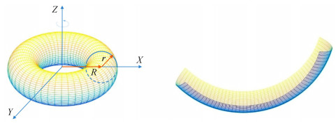
1.1 Toroid mirror and focusing characteristic
As shown in
![]()
Figure 1.Schematic diagram of toroid mirror
The toroid surface equation in Cartesian coordinates can be written as [
where R is the major radius, and r is the minor radius. Toroid mirror is a part of the concave surface, and the base arc can be defined as
where kx is the conic constant, and Ai is polynomial aspheric coefficients. Usually the meridian radius of curvature R is typically quite large (105 mm for our mirror) in comparison with sagittal radius of curvature r, so a toroid mirror becomes a feasible approximation to the ideal ellipsoidal figure. Its advantage is that a single mirror can be used to achieve two-dimensional focusing imaging instead of KB structure. It is of a simple structure and can constitute a multi-channel system. In addition, toroid mirrors could be more easily polished than quadratic surfaces.
It can be seen that the toroid mirror also has an axis of rotational symmetry, but it does not coincide with the axis of the optical system. Toroid mirror is a feasible approximation to the ideal ellipsoidal mirror when the meridian radius of curvature R is typically quite large in comparison with all the other dimensions of the microscope. Because the toroid mirror has different radius of curvature in meridian plane and sagittal plane, it can be considered separately when focusing. The focused imaging on the meridian plane is essentially the same as the imaging characteristics of a spherical mirror, which has been analyzed in many literatures[
The best way to focus the beam with a single element is the use of a toroid mirror with unity magnification (Rowland configuration), which cancels the astigmatism and the coma. However, when a big magnification is required, coma aberration is unavoidable. Therefore, two toroid mirrors are used to improve the coma caused by the single toroid mirror which does not satisfy the Abbe sinusoidal condition, so as to improve the imaging quality of the off-axis point.
1.2 Initial parameters of optical structure
As an imaging optical system, the aim of the proposed configuration is to provide a high resolution image of the X-ray source with the following primary concerns.
The focal length and diameter of the mirrors determine not only the size of the system, but also the resolution of the optical system. Because the energy ICF is high, the environment surrounding the micro ball of Deuterium (D) and Tritium (T) nuclei is more complex. It's better to place the imaging system in a place far from the target, avoiding the damage of high energy beams and debris. Therefore, the object distance of the microscope is better more than 500 mm. At the same time, considering the limitation of the space for installing the microscope, assuming the magnification 15×.
When design the grazing incidence optics, the glancing angle must firstly be decided at the center points of the mirrors.The critical angle of reflection depends on the surface material and wave length of the X-ray. As the wavelength of X-rays becomes shorter and shorter, the critical angle of reflection is extremely small. However the mirrors should have sufficient reflectivity at a large grazing angle. And the design of the grazing angle should take into account the float of the incident angle because of the off-center edge of the mirrors. The grazing incident angle is set to θ=0.5°, achieved by using the multilayer.
The field of view of the microscope is determined by the size of the implosion compression region, which is only several microns, the ideal Field of View (FOV) restricted to 1 mm will be sufficient.
The structure of X-ray microscope is shown in
![]()
Figure 2.Schematic diagram of X-ray imaging system
Since the third mirror is plane who only deflects the optical axis and does not focus the light, only the first two toroid mirrors are considered in the calculation of the initial structural parameters. As shown in
![]()
Figure 3.Reflective imaging diagram of double toroid mirrors
And the magnification can be approximately defined as M=∠A/∠A′=15, combined with the Eq. (3), we got ∠A=1.875°, ∠A′=0.125°. Assuming that the distance from the object A to the center of the first toroid mirror O1 is p1=AO1=740 mm, and the distance between the two mirrors is d=O1O2=120 mm, then according to the triangle cosine relation, it can be calculated that the distance from the center of the second mirror O2 to the image A′ is q2=A′O2=11 938 mm. The object distance p2 of the second mirror and the image distance q1 of the first mirror satisfy the following equation
The total magnification M of the microscope and two toroid mirrors' respective magnification M1 and M2 meet the following requirements
Then the following quantity can be figured out: q1=-1 589 mm, M1=2.14, M2=6.985.
In the case of grazing incidence, the optical axis of the thin beam does not coincide with the normal line of the mirror on the incident point, and the light is no longer a concentric beam after reflection by the optical system, which is focused in the meridian and sagittal direction respectively, and its relationship satisfies the Young′s formula
where pm and qm are the object distance and image distance in the meridian plane respectively; ps and qs are in the sagittal plane; i is the incident angle and i′ is the exit angle; n and n′ are the refractive index of object space and image space. R is the radius of meridian curvature of the toroid mirror and r is the radius of sagittal curvature. Then the grazing incident angle θ=π/2-i, i′=i, n′=-n, pm=ps=p. According to Eq. (8) and Eq. (9), the meridian focal length fm and sagittal focal length fs of a toroid mirror can be obtained.
During the optical design of the microscope, associated with the initial structural parameters (p, M, θ, d), a unique set of toroid mirrors' parameters could be established. In order to make the object be imaged on the same position both on meridian plane and sagittal plane, the focus of both direction should be equal:
which is substituted into Eq.(8) and Eq.(9), then we get the meridian radius of the first mirror R1 and sagittal radius r1 respectively.
In the same way, we get the radius of the meridian plan R2 and radius of sagittal plane r2 of the second mirror.
This is not the only solution for the microscope structure. A set of toroid mirrors with appropriate radius of curvature can be calculated with different grazing angles, object distances, magnification and spacing of mirrors.
1.3 Optimization
The optical system can be optimized after the determination of the initial structure. Since the optical system of the grazing incidence structure is not coaxial, and the chief optical axis rotates at the break point during modeling, the grazing incidence reflection belongs to the large off-axis of the optical element, and the toroid mirror belongs to aspherical mirror, so the default evaluation function and constraint conditions cannot be used for the optimization by ZEMAX.
The mirror length l1 of the first toroid mirror is an adjustable quantity whose length is determined by the expected spatial resolution and the geometric light gathering angle. To some extent, increasing l1 can improve the light collection efficiency of the system, but it will damage the off-axis image quality. The second toroid mirror length l2 can be adapted according to the first mirror length l1, so that all (or part) of the incident light is received and reflected. A proper shortening of l2 can act as an aperture and further improve off-axis aberration.
The radius of meridian curvature, radius of sagittal curvature of the two toroid mirrors, the distance between toroid mirrors, and object distance, image distance are all variables.The optimal evaluation function measures the imaging quality of the system by minimizing the spot radius of the image plane. The on-axis performance is modestly degraded and uniformly aberrations distributed over a chosen object field. The Spot diagram of the optimized system is shown in
![]()
Figure 4.Spot diagram on image plane
Obviously, the spot size is sufficiently bigger than the Rayleigh limit and the microscope belongs to the large aberration system. Spot diagram is still a feasible method to evaluate the imaging quality of large aberration system, which can show the concentration and dispersion degree of point source on the image plane. According to the design parameters, ZEMAX is used to simulate the performance of the microscope, and the spot diagrams of different field of view are calculated. As shown in
2 Analysis
2.1 Aberrations
The biggest advantage of the reflective imaging system is with no chromatic aberration. Compared with axisymmetric optical systems (without considering high order aberrations), The aberrations cannot be analyzed by the software ZEMAX exactly, the primary aberration of off-axis reflection optical system is still spherical aberration, coma astigmatism, etc. However, coma includes linear coma and constant coma, while astigmatism contains quadratic, linear and constant terms. The pseudo axis is regarded as the optical axis, actually, incident rays are all off axis.
2.1.1 Spherical aberration
For a single toroid mirror, since the radius of meridian curvature is much larger than the radius of sagittal curvature, the spherical aberration is mainly sensitive to the meridian surface. The aperture longitudinal aberration is
where α is the aberrant angle of the reflection ray to the center of the mirror.
As shown in
![]()
Figure 5.Longitudinal spherical aberration of single or two toroid mirrors
with the grazing incidence angle same and mirrors 1 and 2 facing.
2.1.2 Coma aberration
Due to the different magnification M of each point on the image plane, off-axis focusing is degraded, especially when the object deviates from its principal axis, and when the grazing incidence angle is small. The coma influence cannot be ignored. For a toroid mirror, the change of the scaling ratio of the beam across the length of the mirror is
As can be seen from the coma aberration formulas above, the aberrations of the toroid mirror focusing image depends on the length l of the mirror illuminated by the beam, the grazing incidence angle θ, the distance p from the mirror to the source, and the magnification M. The coma aberration can be reduced with small mirror size or large object distance.
The first mirror introduces coma, which is completely compensated by the second one, so the coma is mutually compensated with two successive mirrors configuration.
2.1.3 Field obliquity
As shown in
![]()
Figure 6.The character of the two toroid mirrors
2.1.4 Astigmatism
The only condition for overcoming astigmatism in the use of a single toroid mirror is r/R=sin2θ, which is completely satisfied for the point on the axis, but with the increase of the field of view, the off-axis point will cause the change of the grazing incident angle, so that the sagittal and meridian image distances are not equal, and the astigmatism will appear again.
The optical structure is non-axial symmetrical, so off-axis aberration exists. When off-axis aberration has the same order of magnitude as spherical aberration, only correcting spherical aberration of points on the axis cannot guarantee the best performance of the system in the whole field of view.
2.2 Errors analysis and tolerance
In the actual assembly process, there will be errors in the parameters of each mirrors and their positions in the system, which will reduce the imaging quality of the system. Therefore, machining and assembly tolerances should be determined by the allowable quality reduction limit.
To determine the effect of each misalignment on the image quality, spot diagram in the image plane were calculated for various misalignment conditions. There are mainly four misalignment parameters: the grazing incident angle, the angle between the two toroid mirrors, the distance between the toroid mirrors, the distance from the object to the first toroid mirror.
It can be seen from the
![]()
Figure 7.The influence of parameters on the performance of microscope
Besides the parameters analyzed above, other parameters change independently, and we evaluate the range of each tolerance, the central field resolution should be less than 2 μm under the tolerance. Then, we adjusted the tolerance so that 80% of the microscope resolution remained below 5 μm in the whole field. This calculation was obtained by randomly selecting the optical location of 60 000 previously calculated tolerances of different configurations. The final tolerances for positioning are summarized in
| M1 | M2 | M3 | |
| Translation along the | 200 | 200 | 500 |
| Translation along the | 50 | 50 | 50 |
| Translation along the | 200 | 200 | 1 000 |
| Rotation around the | 0.01° | 0.01° | 0.01° |
| Rotation around the | 0.01° | 0.01° | 0.01° |
| Rotation around the | 0.1° | 0.1° | 0.1° |
Table 1. Positioning tolerances of each mirrors
The image resolution is highly sensitive to the mirror figure. Slope errors is the error between the rugged reflecting surface and the ideal smooth surface.The coating material of the mirror is Pt, and the RMS surface roughness of the mirrors was assumed to be 0.5 nm.
3 Alignment
The microscopy system is a grazing incident imaging system which is non-axisymmetric.The accuracy of grazing angle is of great influence on imaging quality. It is difficult to achieve high accuracy by the common method used in the rotational axisymmetric structure under the condition of limited space.
3.1 Off-line mirrors mounted
Since the mirrors of microscope (including M1~M3) is to be installed in the chamber of laser fusion, the space of the chamber is quite limited, and the system requires a highly small grazing incident angle, so the installation and adjustment of the mirrors are typical difficult. Off-line adjustment is mainly to precisely align three mirrors. The fine alignment of the optical system was carried out by especially adjusting the glancing angle to mirror M1 and M2 respectively.
As shown in
![]()
Figure 8.Auxiliary adjustment system
3.2 On-line optical alignment
Off-line mounting ensures that the internal optical elements of the microscope be installed in place, and then online alignment is required to realize that the microscope aim at the center of the object. The microscopic system is different from ordinary optical instruments in that its object and image are not in the same horizontal plane. In addition, the microscopy is installed in the chamber of laser fusion whose space is limited, causing a lot of difficulties in setting and adjusting. The binocular intersection aiming lasers is designed to realize the optical system aiming through the spatial intersection of two laser beams. For the space of the target chamber is limited, the opening angle of the two laser beams can not be too large.
The aiming structure of object and image planeis shown in
![]()
Figure 9.Schematic diagram of microscope aiming section
Image quality evaluation of binocular vision aiming system is shown in
![]()
Figure 10.Optical structure of binocular vision aiming system
![]()
Figure 11.Image quality evaluation of binocular vision aiming system
4 Experiment and result
The source is an X-ray tube open Mo target with metal materials as the anode and filament as the cathode, and its maximum voltage is 50 kV and current is 1 mA. The imaging detector is a PI1 300×1 340 X-ray CCD camera with pixel size of 20 μm.
![]()
Figure 12.Backlight image of a Ni mesh grid and resolution of the image
5 Conclusion
According to the spatial resolution requirements of ICF optical diagnosis and the limitation of experimental space, the X-ray microscope based on the toroid mirrors is designed and optimized. The imaging simulation shows that the spatial resolution of the optimized system is less than 5 μm in the range of 1 mm field of view. Backlight experiments show that the resolution of the system is about 5 μm at 500 μm. The errors between experimental results and simulation results are mainly due to the influence of mirror shape accuracy and diffraction effect. The microscope basically meets the requirements of large field of view and high resolution in laser plasma X-ray imaging. The following work direction is multi-light path structure design to gather more information at the same time, and the design of the multilayer, for the increase of the grazing incidence angle would be useful for image-forming in the hard X-ray region.
References
[3] CAILLAUD T, ALOZY E, BRIAT M, et al. Recent advance in target diagnostics on the Laser Méga Joule (LMJ)[C]. SPIE, 2016: 996606.
[4] Shao-en JIANG, Feng WANG, Yong-kun DING. Experimental progress of inertial confinement fusion based at the ShenGuang-Ⅲ laser facility in China. Nuclear Fusion, 59, 102308(2018).
[8] J K VOGEL, M J PIVOVAROFF, B KOZIOZIEMSKI. Design and raytrace simulations of a multilayer-coated Wolter x-ray optic for the Z machine at Sandia National Laboratories. Review of Scientific Instruments, 89, 10G(2018).
[12] CHEN Shenghao, MU Baozhong, MA Shuang, et al. Design of hard Xray focusing telescope with a large field of view[C]. SPIE, 2014: 92721R.
[13] Lin LI, Yi-fan HUANG, Yong-tian WANG. Modern optical design, 354(2018).
[15] SUZUKI Y, TAKEUCHI A. Crection of spherical aberration in grazingincidence Xray optics by combination of sphericalconcave mirrs[C].AIP Conference Proceedings, 2011, 1365: 156159.


Set citation alerts for the article
Please enter your email address

© Copyright 2018-2021 | Chinese Laser Press. All Rights Reserved 沪ICP备15018463号-20