
Haihua Wu, Junchao He, Yafeng Li, Lei Zhong. Selective Laser Sintering of Natural Flake Graphite Prototype Forming Process Research[J]. Laser & Optoelectronics Progress, 2021, 58(9): 0914005
- Laser & Optoelectronics Progress
- Vol. 58, Issue 9, 0914005 (2021)
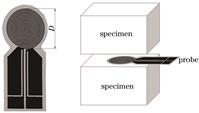
Fig. 1. Schematic of transient plate heat source method
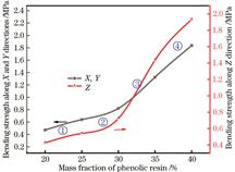
Fig. 2. Effect of phenolic resin addition amount on the bending strength of graphite molded parts
Fig. 3. Curves of increasing range in bending strength of graphite molded parts
Fig. 4. Cross-sectional view of natural flake graphite SLS molded parts along the X, Y, and Z directions when the mass fraction of phenolic resin is 20% and 35%. (a) 20%, X and Y directions; (b) 20%, Z direction; (c) 35%, X and Y directions; (d) 35%, Z direction
Fig. 5. Influence of the phenolic resin addition amount on the forming accuracy of graphite molded parts
Fig. 6. Influence of the phenolic resin addition amount on the thermal conductivity and bulk density of the powder
Fig. 7. Influence of the particle size of natural flake graphite on the bulk density and bending strength (Z direction)of graphite molded parts
Fig. 8. Influence of the particle size of natural flake graphite on the forming accuracy of graphite molded parts
Fig. 9. Influence of the particle size of natural flake graphite on the thermal conductivity of mixed powder
Fig. 10. Influence of coating times on the powder bulk density and the bending strength(Z direction) of graphite molded parts
Fig. 11. SEM images of natural flake graphite and powder after coating twice. (a) Natural flake graphite; (b) powder after coating twice
Fig. 12. Influence of coating times on the forming accuracy of the samples
Fig. 13. Influence of coating times on the thermal conductivity of mixed powder
Fig. 14. CAD modeling of graphite skeleton with diamond-like structure
Fig. 15. SLS molded part of graphite skeleton with diamond-like structure

Set citation alerts for the article
Please enter your email address
© Copyright 2018-2021 | Chinese Laser Press. All Rights Reserved 沪ICP备15018463号-20