Abstract
Due to their good color rendering ability, white light-emitting diodes (WLEDs) with conventional phosphor and quantum dots (QDs) are gaining increasing attention. However, their optical and thermal performances are still limited especially for the ones with QDs-phosphor mixed nanocomposites. In this work, we propose a novel packaging scheme with horizontally layered QDs-phosphor nanocomposites to obtain an enhanced optical and thermal performance for WLEDs. Three different WLEDs, including QDs-phosphor mixed type, QDs-outside type, and QDs-inside type, were fabricated and compared. With 30 wt. % phosphor and 0.15 wt. % QDs nanocomposite, the QDs-outside type WLED shows a 21.8% increase of luminous efficiency, better color rendering ability, and a 27.0% decrease of the maximum nanocomposite temperature at 400 mA, compared with the mixed-type WLED. The reduced re-absorption between phosphor and QDs is responsible for the performance enhancement when they are separated. However, such reduced absorption can be traded off by the improper layered configuration, which is demonstrated by the worst performance of the QDs-inside type. Further, we demonstrate that the higher energy transfer efficiency between excitation light and nanocomposite in the QDs-outside type WLED is the key reason for its enhanced optical and thermal performance.1. INTRODUCTION
Due to their high efficiency, low power consumption, long lifetime, and environmental friendliness, white light-emitting diodes (WLEDs) are replacing traditional incandescent and fluorescent lamps to become next-generation lighting sources in general lighting, automotive lighting, and display backlight [1–3]. The most common method to produce WLEDs is to combine GaN LED chip with (YAG) yellow phosphor. Such WLEDs suffer from a low color rendering index (CRI, ) due to the absence of red component in the emission spectra of YAG phosphor [4]. To enhance the red emission and further color rendering ability, red emissive phosphors are usually mixed with yellow phosphor. With the improved efficiency and optimized layered structure, the WLEDs with YAG and red phosphors are now commercially available [5,6]. However, they are still unable to achieve a high luminous efficiency (LE) because the deep red component (wavelength ) of red emission is beyond the sensitive region of the human eye [7].
More recently, colloidal quantum dots (QDs), with obviously different characteristics of narrow emission spectra, wide absorption spectra, and solution-processed characteristics from conventional inorganic phosphor, have attracted much attention to become a promising alternative to conventional phosphor as color converting material in WLEDs [8–10]. Several types of QDs, including CdSe, InP, , C, , and and so on, are now attracting increased attention. Among them, the most mature one is CdSe, which is also commercially available. CdSe QDs, belonging to II–VI group semiconductors, have a quite narrow full width at half-maximum (FWHM) (20–30 nm) and super high quantum efficiency (). Another aspect is that CdSe QDs can be tuned to cover the entire visible region by tailoring the particle size. Based on the above aspects, CdSe QDs are finding many applications in LEDs, including backlight display and general lighting [11]. It is well noted that the first commercial QDs-based WLED in an on-chip configuration is also based on CdSe QDs [9]. However, the Cd element is quite toxic to humans in CdSe QDs, which hinders their wide applications. Therefore, Cd-free QDs are developed to overcome the toxicity problem, including InP, , and carbon QDs. Compared with CdSe QDs, InP and QDs are still less efficient and exhibit wider FWHM [11,12]. In regard to carbon QDs, they are still difficult to emit long-wavelength emission, such as red emission [13]. Recently, perovskite QDs, including and QDs, are emerging as promising light emitting materials with high efficiency and superb color purity, particular in green color [14]. Compared with CdSe QDs, perovskite QDs have narrower FWHM and can be adjusted to different emission wavelengths by composition tuning. However, the stability under the air condition of perovskite QDs is still a problem that needs to be solved, especially for those red or blue perovskite QDs [15]. Overall, red CdSe QD is still a good choice for enhancing the CRI of conventional WLEDs.
For most QDs-based WLEDs, remote phosphor configuration, which separates the QDs plate from LED chip, is preferred due to several advantages, such as high efficiency and improved photon and thermal stability [16,17]. When phosphor and QDs are mixed together to serve as a light-converting layer, WLEDs still suffer a bad optical and thermal performance due to the reabsorption problem between phosphor and QDs and low energy transfer efficiency between excitation light and color converting materials [18]. To overcome such problems in the mixed-type WLEDs, a vertically layered packaging structure, where phosphor and QDs layers are separated vertically, was proposed to enhance the optical and thermal performance of WLEDs [18–21]. In Refs. [18,20], it was indicated that the phosphor layer should be placed near the LED chip, considering a higher quantum yield of phosphor than QDs and the layer adjacent to the LED plays a major role in the color conversion. Both works showed that QDs-on-phosphor type exhibited higher LE, CRI, and lower WLED temperature than the mixed type and phosphor-on-QDs type. Therefore, the QDs-on-phosphor type was considered as an excellent solution to obtaining WLEDs with better optical and thermal performance. However, it should be noted that the reabsorption problem is not solved in such a packaging structure because the green or yellow light emitted by phosphor can still be absorbed by red QDs when it passes through the QDs layer. In addition, the energy transfer efficiency between blue light and the phosphor or QDs layer is not the same across the layer surface because LED has a Lambertian intensity distribution, which peaks in the center while showing a quite low value in the edge [22]. Until now, the packaging structure across the horizontal surface has not been considered. Herein, we propose a horizontally layered packaging structure for QDs phosphor nanocomposite to solve the reabsorption and low energy transfer problems simultaneously. It is demonstrated that the horizontally layered QDs phosphor nanocomposite can significantly enhance the optical and thermal performance of WLEDs. To make a good comparison, we have fabricated three types of WLEDs, including QDs-phosphor mixed type, QDs-outside type, and QDs-inside type, and measured their optical and thermal characteristics for various QDs-phosphor concentrations.
Sign up for Photonics Research TOC. Get the latest issue of Photonics Research delivered right to you!Sign up now
2. EXPERIMENTS AND MEASUREMENT
A. Preparation of WLEDs with QDs Phosphor Nanocomposites
For the preparation of WLEDs, blue LEDs (Foshan Nationstar, type 3535) were chosen as pump sources of the QDs phosphor nanocomposites. QDs and phosphor mixtures were deposited on the total internal reflection (TIR) lens with a diameter of 12 mm and a height of 7 mm, as shown in Fig. 1(a). In this study, we introduced the mixed type, QDs outside type, and QDs inside type to be compared, as shown in Figs. 1(b)–1(d). For the QDs-outside type and QDs-inside type, a concentric ring configuration with an inner diameter of 8.5 mm was used to keep the same inside and outside areas. In detail, the QDs-outside type has red QDs deposited on the outside ring, while the QDs-inside type has QDs deposited on the inside circle. The QDs and phosphor mixtures of both nanocomposites have been separated. The red QDs used in this study are CdSe/ZnS core-shell structure QDs with a photoluminescence (PL) quantum yield of (Suzhou Xingshuo Nanotech Co., Ltd). For the fabrication of QDs mixture, a QDs-chloroform solution with a concentration of 25 mg/mL was first added into polydimethylsiloxane (PDMS, Dow Corning Sylgard184) to form a pre-blending mixture, which was then subjected to high-speed centrifugal stirring. The stirring worked to disperse QDs into PDMS and induce solvent evaporation. After a 30-min stirring process, the curing agent (Dow Corning Sylgard184 silicone elastomer curing agent) was added into the above mixture at a weight ratio of with the silicone, followed by further stirring under vacuum. In regard to the phosphor mixture preparation, YAG phosphor (Intermatix YAG04) was used to be blended with PDMS and its curing agent and then subjected to a centrifugal stirring under vacuum to form a uniform phosphor-silicone mixture. The weight ratio between phosphor and QDs was kept as 200 during the experiments. The phosphor weight ratios used in the experiments were 20%, 30%, and 40%, respectively. Correspondingly, the QDs weight ratios were set as 0.1%, 0.15%, and 0.2%, respectively. The three different phosphor-QDs configurations were used to obtain different CCTs for WLED devices to be compared.
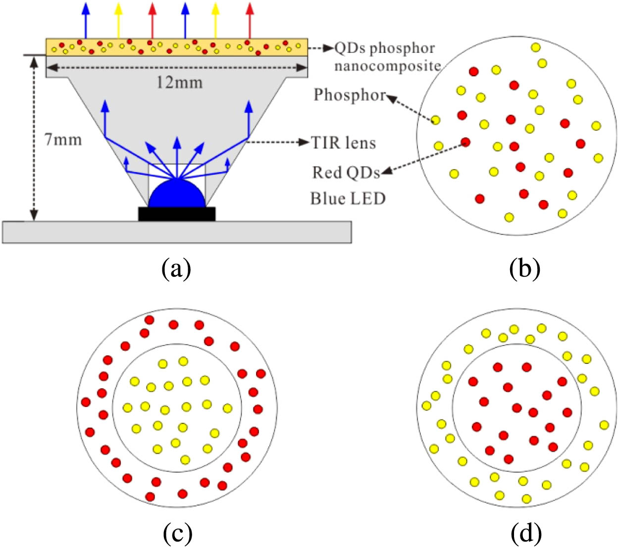
Figure 1.(a) Diagram of WLED device with QDs phosphor nanocomposite. (b) Mixed type. (c) QDs-outside type. (d) QDs-inside type.
In the experiment, the nanocomposite film thickness of the three WLED devices was kept as 0.8 mm. For the fabrication of mixed-type WLED, QDs and phosphor mixtures were blended together then dropped cast and cured (nanocomposite curing condition: 120°C at 1 h) on the top surface of a TIR lens. In addition, the fabrication process of horizontally layered quantum dots phosphor nanocomposite is shown in Fig. 2, where the QDs-outside type was set as an example. A steel mold with an inner diameter of 8.5 mm and a Teflon mold with an inner diameter of 12 mm were used in the experiment, as shown in Fig. 2(a). After the assembling of the parts, yellow phosphor was first dispensed and cured on the inner circle of the TIR lens. Then, the steel mold was removed, and red QDs were dispensed and cured on the outside region of TIR lens. In the end, the Teflon mold was removed and the QDs-phosphor nanocomposite was obtained. The bare LED without any phosphor or QDs and fabricated WLEDs with different QDs-phosphor nanocomposites are shown in Fig. 3.

Figure 2.Fabrication process of horizontally layered quantum dots phosphor nanocomposite (QDs-outside type): (a) molds and TIR lens, (b) parts assembling, (c) phosphor coating, (d) steel mold removing, (e) QDs coating, and (f) Teflon mold removing.
Figure 3.(a) LED device without QDs-phosphor nanocomposite. (b)–(d) LED devices with different QDs-phosphor nanocomposites: mixed type; QDs-outside type; QDs-inside type.
B. Characterizations
QDs samples for transmission electron microscopy were prepared by dropping a diluted dispersion of QDs-chloroform solution on a carbon-coated copper grid, followed by a solvent evaporation process under heated condition. Transmission electron microscopy images were recorded by a JEOL JEM-2100F (JEOL, Tokyo, Japan) microscope.
The excitation spectra and PL spectra of YAG:Ce phosphor and CdSe/ZnS core-shell QDs were characterized by a spectrofluorophotometer (Shimadzu RF-6000). The optical power, luminous flux, emission spectra, and CRI of WLED devices were measured in a 0.5 m diameter integrating sphere (Otsuka LE5400) at a driving current range from 100 to 700 mA with a 100 mA step. During the measuring process, the WLED devices were powered by a Keithley 2450 DC source. The thermal images were recorded by a thermal IR-camera (FLIR ThermaCAM SC300 with the thermal sensitivity of 0.02 K).
3. RESULTS AND DISCUSSION
Figure 4(a) shows the high-resolution transmission electron microscope (TEM) images of the CdSe/ZnS core-shell QDs, which have an average diameter of 10.3 nm with quite uniform size distribution. The excitation and PL spectra of QDs and phosphor are shown in Fig. 4(b). It is noted that the red QDs have an extremely wide excitation spectra varying from 380 nm to , whereas YAG phosphor has an excitation peak at . Because the LED chip used in this work has a peak emission wavelength at , the QDs and phosphor can be well excited to generate red and yellow emission, respectively. The PL spectrum of QDs peaks at and has a narrow FWHM of 30 nm, which demonstrates the uniform size distribution of QDs particles. Additionally, the yellow phosphor has a wide PL spectrum with an FWHM of 118 nm peaking at 544 nm, which overlaps with the excitation spectrum of QDs. Therefore, the reabsorption of yellow emission by QDs should be obvious in the mixed type, which has been demonstrated in the previous literatures [18,21].
Figure 4.(a) High-resolution TEM images of the CdSe/ZnS core-shell QDs. Inset: photograph of QDs solution under UV light exposure. Scale bars: 30 nm, 5 nm. (b) Excitation and PL spectra of YAG phosphor and QDs.
Figure 5 illustrates the current-dependent optical power, LE and luminous efficacy of optical radiation (LER) of three WLED devices. LE is defined as the luminous flux per electrical power, while LER is defined as the luminous flux per optical power and illustrates the efficiency of the LED radiation. In detail, the LE and LER are expressed as follows: where 683 lm/W is the largest LER at 555 nm, is the human eye sensitivity function, and is the emission spectrum of WLED. and denote the applied current and voltage of blue LED. Here, we set the integrating wavelength range as [360, 830 nm].
Figure 5.Optical power, LE and LER of the three WLED devices at varying current from 100 mA to 700 mA.
As shown in Fig. 5, the optical power values increase with the driving current, while the LE shows a descending trend, and the LER also exhibits a slightly decreasing trend. Moreover, the QDs-outside type has the highest optical power, LE, and LER among the three WLEDs. At 400 mA, the optical power, LE, and LER of QDs-outside type WLED are 310.4 mW, 71.6 lm/W, and 286.9 lm/W, which are 11.2%, 21.8%, and 9.1% higher than the mixed-type WLED, respectively. The increasing power and flux are attributed to reduced re-absorption by QDs and optimized packaging scheme. Additionally, it is interesting that the WLEDs with horizontally layered nanocomposites do not always show better performance than the mixed-type WLED. In contrast, the QDs-inside type WLED exhibits a worse performance in the LE (36.6% lower) and LER (40.9% worse) than the mixed type, which does not separate QDs and phosphor and has a larger re-absorption of yellow emission by QDs.
In order to better understand the optical performance difference between these three WLEDs, we measured the emission spectra with the varying current from 100 mA to 700 mA with a 100 mA step. Figure 6 shows the normalized emission spectra, the calculated separated power, and color conversion efficiency (CCE, defined as the ratio between the emission from the nanocomposite to the absorbed blue emission) of three WLEDs at 400 mA. Because of the red emission from QDs and the yellow emission from YAG phosphor overlap, the red emission cannot be calculated by the direct integration of the red spectrum. Therefore, we can obtain red emission by subtracting yellow emission from the white light spectrum. Since the yellow emission shape from QDs-phosphor agrees well with the one from the phosphor, the yellow emission from the nanocomposite can be calculated by multiplying a coefficient , which is defined as the ratio of the intensity at peak yellow emission wavelength between yellow emission from the nanocomposite and reference configuration. Therefore, the yellow emission power and red emission power can be calculated as the following: where , are the emission spectra of reference WLED only with YAG phosphor and WLED with nanocomposite, respectively. Here, we set the integrating wavelength range as [490, 830 nm].
Figure 6.(a) Normalized emission spectra of three WLED devices (mixed type, QDs-outside type, and QDs-inside type) at 400 mA. Inset shows the corresponding optical characteristics. (b) Their separated emission power (blue emission, YAG emission, and QDs emission).
In addition, the CCE can be calculated as follows: where and are the excitation power of blue LED and the blue emission power of WLED, respectively.
As shown in Fig. 6(a), the spectra at the wavelength range of visible light (380–780 nm) are quite different for the three WLEDs. Compared with the mixed-type WLED, the QDs-outside-type WLED has larger peak intensities in the blue and yellow emissions while lower peak intensity in the red emission. As shown in Fig. 6(b), the blue, YAG, and QD emissions of mixed-type WLED are 85.5, 131.6, and 62 mW, respectively. Those corresponding values of QDs-outside type are 98, 178.2, and 34.5 mW, respectively. The CCE of QDs-outside-type WLED is 46.1%, which is 13% higher than that of mixed-type WLED (40.8%). It can be indicated that the energy transfer of QDs-outside-type WLED is more efficient than that of the mixed type. In regards to the QDs-inside-type WLED, the corresponding power values are 165.2, 62, and 71 mW, respectively. The yellow emission of QDs-inside-type WLED is so low that it shows the worst optical performance (lowest in LE and LER, no CCT and Ra). Its CCE is the lowest (33.7%), which means its energy transfer efficiency is the least. From the above values, we can conclude that the energy transfer from blue LED to yellow phosphor is more efficient than that from blue LED to red QDs. In addition, the mixed-type WLED has a lower CCT (4447 K) than the QDs-outside type WLED, which is attributed to the more produced red emission in the mixed-type WLED. And both devices have similar Ra values higher than 80, which is an essential prerequisite for indoor and medical lighting. Another important CRI parameter is R9, which represents the ability of WLED to render the red component of an object. A higher R9 value means better performance to exhibit red color. Though the QDs-outside type WLED has a similar Ra with the mixed type, the QDs-outside type shows a significant increase in R9 value, which is even higher than 80. Though the QDs-outside-type WLED shows a better performance in light output and R9 value, the improper separated QDs-phosphor nanocomposite can bring a contrary result. The QDs-inside type WLED has the lowest LE and LER values among the three types of WLEDs and has no Ra or R9. To illustrate the color difference of three types of WLEDs, we also took the photo images of three WLEDs under the lighting conditions shown in Fig. 7. From the photo images, we can see that an obvious red ring can be viewed in the mixed-type and QDs-inside-type WLEDs, while such red-ring phenomenon is not pronounced in the QDs-outside-type WLED. In fact, the color coordinate (0.3281, 0.3049) of the QDs-outside WLED is nearer to the Planckian locus in the 1931 chromaticity diagram than those of the other two types of WLEDs, which indicates that the proposed QDs-outside-type WLED is more suitable for general illumination.
Figure 7.CIE color coordinates in the 1931 chromaticity diagram of mixed type, QDs-outside type, and QDs-inside type WLEDs and corresponding photo images at an operating current of 400 mA.
Furthermore, the different optical performance of three WLEDs is explained as follows. We attributed such optical difference to two aspects: one is the reabsorption phenomenon between yellow phosphor and red QDs; the other, which we think is the main reason, is the energy transfer efficiency between the excitation blue light and the phosphor-QDs nanocomposite. For the mixed-type WLED, there exists a large reabsorption of green or yellow light by red phosphor, which brings a large energy loss [6,23–25]. Such reabsorption phenomenon is more severe when red QDs are introduced because the excited spectra of red QDs overlap greatly with the emission spectra of yellow phosphor. To demonstrate the reabsorption phenomenon, we have used the yellow LED, which includes a blue LED and saturated phosphor, to excite the red QDs. The experimental setup can be viewed in the inset of Fig. 8. As shown in Fig. 8, the spectrum of yellow LED does not witness a blue part, which means all of the blue light from LED chip is absorbed by yellow phosphor and converted to yellow emission. After red QDs are coated on the TIR lens, the original spectrum shows a lower intensity and has an intensity increase around 620 nm (marked as red part) on the basis of yellow spectrum. The red part is actually the red emission from the coated QDs. Because the yellow LED emits no blue emission, the red QDs can only absorb the converted yellow emission to re-emit the red emission, which demonstrates the reabsorption phenomenon between the yellow phosphor and red QDs in the mixed-type WLED. The results are also consistent with the reported literatures [18,21]. Such reabsorption phenomenon lowers the efficiency of WLED because the converted efficiency is quite less than unity, and the produced red emission is less sensitive to human eyes than the original yellow emission. Hence, when red QDs and yellow phosphor are separated, the reabsorption between QDs and phosphor can be largely reduced, which is also demonstrated in the literatures [18,20,21]. One interesting phenomenon should be noted that the QDs-inside type has the worst optical performance, though phosphor and QDs are separated, which indicates that reduced absorption is not the main cause of the large performance enhancement of QDs-outside type WLED. We attribute the performance difference between QDs-inside-type and QDs-outside-type WLEDs to their different energy transfer efficiency, which we will discuss later.
Figure 8.Normalized emission spectra of yellow LED and yellow LED with red QDs. Inset: diagram of measuring setup.
Before illustrating the energy transfer efficiency between blue light and phosphor-QDs nanocomposite, we need to ensure the CCE of phosphor and QDs. Based on the experimental setup in Fig. 1, the measured CCEs of 30% phosphor and 0.15% QDs are 55.7% and 35.6%, respectively. Considering the higher efficiency and eye-sensitivity of yellow phosphor than red QDs, it is wiser to transfer blue light energy to phosphor other than QDs to obtain better optical performance. It is well known that LED is a typical Lambertian light source, whose light intensity peaks in the center and dramatically decreases with the increasing of the viewing angle. To demonstrate this, we measured the blue-light intensity distributions of LED component without TIR lens and with TIR lens. As shown in Fig. 9, the FWHM of bare LED intensity is 112°. After the TIR lens is integrated, the central intensity is magnified and the FWHM is reduced to 17°, which indicates that much of the light energy is concentrated to the central region. To figure out the energy distribution across the lens surface, we measured the energy proportion of central region of the lens, which accounts for 80% of the total energy. Therefore, when the phosphor is dispensed on the central region in the QDs-outside type WLED, most of blue light energy can be transferred to the nanocomposite more effectively. At the same time, the red QDs are dispensed on the peripheral region of the lens to reduce the absorption of blue light because QDs are less efficient compared with yellow phosphor. This is the reason why the QDs-outside-type WLED outperforms the mixed-type and the QDs-inside-type WLEDs. For the mixed-type WLED, red QDs are dispensed on the whole lens surface. The red QDs in the center absorb more blue light to generate red emission than those in the edge. The QDs bring lower energy transfer efficiency for the WLED device when accumulated in the center. For the QDs-inside-type WLED, the optical energy transfer efficiency is even lower due to a higher QDs concentration in the center than the mixed type and the lack of phosphor in the center. And the reduced re-absorption in the QDs-inside type WLED can be easily traded off and overpassed by its low energy transfer efficiency between the blue light and QDs-phosphor nanocomposite. The better optical performance of QDs-outside type, compared with the mixed type and QDs-inside type, has demonstrated that red QDs should be positioned in the edge to obtain a high energy transfer efficiency, which is also the main cause of its large performance enhancement.
Figure 9.Normalized light intensity distribution of LED devices without/with lens. Inset: light energy proportion of central region and peripheral region.
Besides light efficiency, the nanocomposite temperature is also an important concern for a WLED device because higher nanocomposite temperature induces phosphor or QDs quenching and accelerates their degradation, especially for red QDs [26]. It has been demonstrated that lowering QDs temperature can help enhance QDs emission and improve light efficiency [27]. Therefore, here we compare the highest nanocomposites temperature and the highest QDs temperature of the WLED devices at the driving current of 400 mA. The measured WLED devices are shown in Fig. 10(a). Three LED devices in series were connected to keep the same driving current and were fixed on the aluminum plate by heat-conducting adhesive tape to dissipate the heat generated by LED chips. The temperature fields of the nanocomposite layers are shown in Fig. 10(b). All the LED devices have the highest temperature in the center and the lowest temperature in the edge, which corresponds well with the light intensity distribution of blue LED. It is shown that the QDs-outside type has the lowest temperature, while the other two types have higher temperature distributions. In detail, the highest temperature of QDs-outside type is 64.2°C, which is 23.8°C lower than that of the mixed type. Because the red QDs of QDs-outside type are distributed in the edge, its highest temperature of QDs layer, which is only 51.1°C, shows a lower value than the central temperature. It can be anticipated that the QDs-outside type has a better reliability considering a lower temperature of QDs. The horizontally layered configuration does not always show better thermal performance. In contrary, the QDs-inside type suffers from the most severe heat and the highest temperature, which is also the highest temperature of red QDs, as high as 96.6°C. Actually, the red QDs with a lower quantum yield and higher Stokes loss can generate more heat than the yellow phosphor. Therefore, the temperature is higher when they are dispensed in the center and is even the highest for the QDs-inside type. Higher QDs temperature can lower the light efficiency obviously, which is not good for the optical performance of WLED. In addition, the thermal quenching characteristics of QDs are more severe than those of YAG phosphor and QDs also have worse reliability than YAG phosphor; hence, the QDs should be positioned outside to avoid much energy absorption. The temperature results agree well with the optical performance of the three WLEDs and further demonstrate that a proper horizontally layered configuration with red QDs outside is essential to obtaining a better optical and thermal performance.
Figure 10.(a) Photograph of the three lighting WLED devices. (b) Temperature fields of three WLED devices measured by infrared video camera under driving current of 400 mA.
Furthermore, to demonstrate the effectiveness of our results under a general condition, we also conducted other experiments using different phosphor and QDs concentrations. The results are shown in Table 1. When the phosphor concentration is higher, the mixed type or the QDs-outside type can have a lower CCT. For the mixed type and QDs-outside type, their CRIs all exceed 80 and show no obvious difference between them. In regard to R9, the QDs-outside type has a higher value when the phosphor concentrations are higher (30% and 40%) than that in the mixed type. When the phosphor concentration is low (20%), both of them have a similar R9 value. It is well noted that the QDs-outside type always has better optical and thermal performance (higher optical power, LE, LER and lower , ) in the phosphor concentrations ranging from 20% to 40% than the mixed type. With regards to the QDs-inside type, it has no CCT or CRI values in all the phosphor concentrations due to the insufficiency of yellow phosphor excitation. Overall, the QDs-inside-type WLED has the worst performance in the LE and LER values and nanocomposite temperature among the three types of WLEDs. When the phosphor concentration is low (20%), the QDs-inside type still has the highest optical power; however, the power value suffers a dramatic decrease when phosphor and QDs concentrations become higher, which can be explained by a high absorption yet a low emission of QDs. Here, the results further demonstrate the outstanding performance of QDs-outside-type WLED, which mainly benefits from its high energy transfer efficiency between blue light and QDs-phosphor nanocomposite. Of course, the reduced absorption also contributes to the enhancement.
| Type | Phosphor Concentration (%) | Optical Power (mW) | LE/LER (lm/W) | CCT (K) | Ra/R9 | Tmax/TQDmax(°C) |
| Mixed type | 20 | 294.1 | 64.5/273.5 | 5098 | 86.5/75.8 | 76.6/76.6 |
| 30 | 279.1 | 58.8/262.9 | 4447 | 84.7/48.6 | 88.0/88.0 |
| 40 | 264.5 | 56.0/264.2 | 4148 | 86.3/53.9 | 84.4/84.4 |
| QDs-outside type | 20 | 331.7 | 75.0/282.1 | 6656 | 84.4/75.1 | 61.6/51.3 |
| 30 | 310.4 | 71.6/286.9 | 5744 | 85.5/80.8 | 64.2/51.1 |
| 40 | 296.4 | 71.7/302.3 | 4866 | 83.6/61.8 | 63/53.8 |
| QDs-inside type | 20 | 351.8 | 31.8/112.0 | — | — | 73.9/73.9 |
| 30 | 298.2 | 37.3/155.3 | — | — | 96.6/96.6 |
| 40 | 258.4 | 31.2/150.0 | — | — | 105.6/105.6 |
Table 1. Optical and Thermal Characteristics of the Three WLED Devices at 400 mA
4. CONCLUSIONS
This work has systematically studied the optical and thermal performance of three types of WLEDs with different QDs phosphor nanocomposites. It was found that a proper horizontally layered packaging scheme with QDs positioned outside is essential to enhancing the optical and thermal performance of WLEDs. Specifically, the QDs-outside-type WLED, with phosphor and QDs concentrations of 30%–0.15%, exhibits a LE of 71.6 lm/W and LER of 286.9 lm/W at 400 mA with CRI values of and . The corresponding values of the mixed type WLED are , , , and . The QDs-inside-type WLED has an LE of 37.3 lm/W and LER of 155.3 lm/W but has no CCT or CRI values. In regard to the maximum nanocomposite temperature , the temperature values of mixed type, QDs-outside type, and QDs-inside type are 88.0°C, 64.2°C, and 96.6°C, respectively. Because red QDs are positioned outside the lens surface for the QDs-outside type, the maximum QDs temperature (51.1°C) is lower than , and the other two types have the same temperature values for and . We have demonstrated that, when phosphor and QDs are separated, the reabsorption between them is reduced, which can be traded off by the improper position of QDs. Because phosphor has higher conversion efficiency than QDs, the energy transfer between blue light and phosphor is more effective than that of QDs. In addition, the light energy of the central lens region accounts for 80% of the total energy. When phosphor is placed on the central region and QDs are placed outside the phosphor, most of the blue light energy can be transferred to the phosphor in a more effective way. In contrast, the energy transfer is less effective when QDs are placed across the lens surface or on the central region in the mixed-type or QDs-inside-type WLEDs. Therefore, the QDs-outside type, which has the highest energy transfer efficiency and also reduced reabsorption, is an optimal packaging scheme for QDs-based WLEDs in terms of optical and thermal performance.
Acknowledgment
Acknowledgment. The first author Shudong Yu also thanks support and love from Miss Dong Fang on Chinese Valentine’s Day.
References
[1] P. Pust, P. J. Schmidt, W. Schnick. A revolution in lighting. Nat. Mater., 14, 454-458(2015).
[2] S. Yu, Z. Li, G. Liang, Y. Tang, B. Yu, K. Chen. Angular color uniformity enhancement of white light-emitting diodes by remote micro-patterned phosphor film. Photon. Res., 4, 140-145(2016).
[3] J. S. Li, Y. Tang, Z. T. Li, Z. Li, X. R. Ding, L. S. Rao. Investigation of the emission spectral properties of carbon dots in packaged LEDs using TiO2 nanoparticles. IEEE J. Sel. Top. Quantum Electron., 23, 2000507(2017).
[4] H. Zhu, C. C. Lin, W. Luo, S. Shu, Z. Liu, Y. Liu, J. Kong, E. Ma, Y. Cao, R. S. Liu. Highly efficient non-rare-earth red emitting phosphor for warm white light-emitting diodes. Nat. Commun., 5, 4312(2014).
[5] Z. T. Li, Y. Tang, Z. Y. Liu, Y. E. Tan, B. M. Zhu. Detailed study on pulse-sprayed conformal phosphor configurations for LEDs. J. Disp. Technol., 9, 433-440(2013).
[6] S.-P. Ying, J.-Y. Shen. Concentric ring phosphor geometry on the luminous efficiency of white-light-emitting diodes with excellent color rendering property. Opt. Lett., 41, 1989-1992(2016).
[7] X. Piao, K. Machida, T. Horikawa, H. Hanzawa, A. Y. Shimomura, N. Kijima. Preparation of CaAlSiN3:Eu2+ phosphors by the self-propagating high-temperature synthesis and their luminescent properties. Chem. Mater., 19, 4592-4599(2007).
[8] J. Y. Lien, C. J. Chen, R. K. Chiang, S. L. Wang. High color-rendering warm-white lamps using quantum-dot color conversion films. Opt. Express, 24, A1021-A1032(2016).
[9] K. T. Shimizu, M. Böhmer, D. Estrada, S. Gangwal, S. Grabowski, H. Bechtel, E. Kang, K. J. Vampola, D. Chamberlin, O. B. Shchekin, J. Bhardwaj. Toward commercial realization of quantum dot based white light-emitting diodes for general illumination. Photon. Res., 5, A1-A6(2017).
[10] B. D. Mangum, T. S. Landes, B. R. Theobald, J. N. Kurtin. Exploring the bounds of narrow-band quantum dot downconverted LEDs. Photon. Res., 5, A13-A22(2017).
[11] H. Chen, J. He, S. T. Wu. Recent advances on quantum-dot-enhanced liquid-crystal displays. IEEE J. Sel. Top. Quantum Electron., 23, 1900611(2017).
[12] H. Zhong, Z. Bai, B. Zou. Tuning the luminescence properties of colloidal I-III-VI semiconductor nanocrystals for optoelectronics and biotechnology applications. J. Phys. Chem. Lett., 3, 3167-3175(2012).
[13] L. Rao, Y. Tang, Z. Li, X. Ding, G. Liang, H. Lu, C. Yan, K. Tang, B. Yu. Efficient synthesis of highly fluorescent carbon dots by microreactor method and their application in Fe3+ ion detection. Mater. Sci. Eng. C, 81, 213-223(2017).
[14] C. Li, K. Sun, W. Hu, W. Chen, W. Chen, X. Liu, X. Tang, Z. Zang, Z. Hu. Highly pure green light emission of perovskite CsPbBr3 quantum dots and their application for green light-emitting diodes. Opt. Express, 24, 15071-15078(2016).
[15] J. He, H. Chen, H. Chen, Y. Wang, S. T. Wu, Y. Dong. Hybrid downconverters with green perovskite-polymer composite films for wide color gamut displays. Opt. Express, 25, 12915-12925(2017).
[16] Z. Luo, D. Xu, S. T. Wu. Emerging quantum-dots-enhanced LCDs. J. Disp. Technol., 10, 526-539(2014).
[17] L. Yin, Y. Bai, J. Zhou, J. Cao, X. Sun, J. Zhang. The thermal stability performances of the color rendering index of white light emitting diodes with the red quantum dots encapsulation. Opt. Mater., 42, 187-192(2015).
[18] Y. W. Ju, K. Kim, S. Jeong, C. S. Han. Enhanced photoluminescence of layered quantum dot-phosphor nanocomposites as converting materials for light emitting diodes. J. Phys. Chem. C, 115, 20945-20952(2011).
[19] J.-H. Kim, W.-S. Song, H. Yang. Color-converting bilayered composite plate of quantum-dot-polymer for high-color rendering white light-emitting diode. Opt. Lett., 38, 2885-2888(2013).
[20] B. Xie, C. Wei, J. Hao, W. Dan, X. Yu, Y. Chen, R. Hu, W. Kai, X. Luo. Structural optimization for remote white light-emitting diodes with quantum dots and phosphor: packaging sequence matters. Opt. Express, 24, A1560-A1570(2016).
[21] S. Abe, J. J. Joos, L. I. Martin, Z. Hens, P. F. Smet. Hybrid remote quantum dot/powder phosphor designs for display backlights. Light Sci. Appl., 6, e16271(2017).
[22] X. Lei, H. Zheng, X. Guo, J. Chu, S. Liu, P. Liu. Optical performance enhancement of quantum dot-based light-emitting diodes through an optimized remote structure. IEEE Trans. Electron Devices, 63, 691-697(2016).
[23] J. S. Lee, P. Arunkumar, S. Kim, I. J. Lee, H. Lee, W. B. Im. Smart design to resolve spectral overlapping of phosphor-in-glass for high-powered remote-type white light-emitting devices. Opt. Lett., 39, 762-765(2014).
[24] E. Kim, S. Unithrattil, I. S. Sohn, S. J. Kim, W. J. Chung, W. B. Im. Facile one-step fabrication of 2-layered and 4-quadrant type phosphor-in-glass plates for white LEDs: an insight into angle dependent luminescence. Opt. Mater. Express, 6, 804-814(2016).
[25] S. P. Ying, H. Y. Chien. Effect of reassembled remote phosphor geometry on the luminous efficiency and spectra of white light-emitting diodes with excellent color rendering property. IEEE Trans. Electron Devices, 63, 1117-1121(2016).
[26] B. Xie, R. Hu, X. Yu, B. Shang, Y. Ma, X. Luo. Effect of packaging method on performance of light-emitting diodes with quantum dot phosphor. IEEE Photon. Technol. Lett., 28, 1115-1118(2016).
[27] H. Zheng, X. Lei, T. Cheng, S. Liu, X. Zeng, R. Sun. Enhancing thermal dissipation of light-converting composite for quantum dot based white light-emitting diodes through electrospinning nanofibers. Nanotechnology, 28, 265204(2017).


