• Chinese Optics Letters
  • Vol. 18, Issue 5, 052501 (2020)
Simin Li1, Rong Cong1, Zhengqian He1, Tianliang Wang2, Fangzheng Zhang1、*, and Shilong Pan1
Author Affiliations
  • 1Key Laboratory of Radar Imaging and Microwave Photonics, Ministry of Education, Nanjing University of Aeronautics and Astronautics, Nanjing 210016, China
  • 2Shanghai Institute of Satellite Engineering, Shanghai 201109, China
  • show less
    DOI: 10.3788/COL202018.052501 Cite this Article Set citation alerts
    Simin Li, Rong Cong, Zhengqian He, Tianliang Wang, Fangzheng Zhang, Shilong Pan. Switchable microwave photonic filter using a phase modulator and a silicon-on-insulator micro-ring resonator[J]. Chinese Optics Letters, 2020, 18(5): 052501 Copy Citation Text show less
    Schematic diagram of the proposed microwave photonic filter. TLS, tunable laser source; PC, polarization controller; PM, phase modulator without a polarizer; MRR, micro-ring resonator; PD, photodetector; VNA, vector network analyzer.
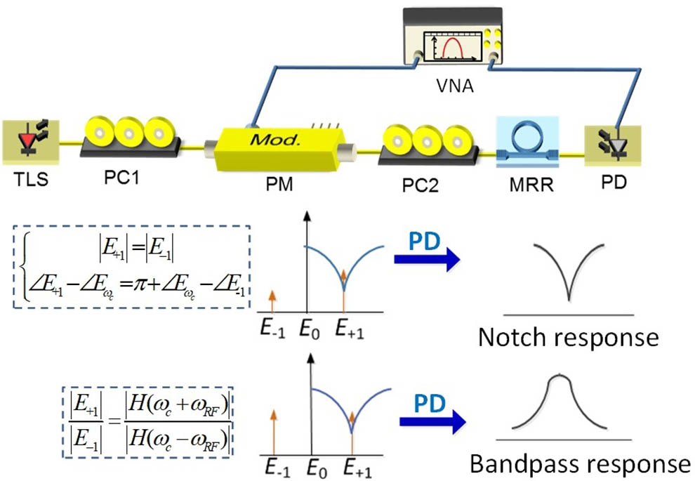
    Fig. 1. Schematic diagram of the proposed microwave photonic filter. TLS, tunable laser source; PC, polarization controller; PM, phase modulator without a polarizer; MRR, micro-ring resonator; PD, photodetector; VNA, vector network analyzer.
    Normalized magnitude and phase response of the MRR. Inset: the MRR used in the experiment.
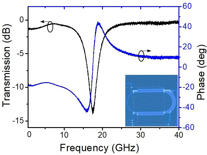
    Fig. 2. Normalized magnitude and phase response of the MRR. Inset: the MRR used in the experiment.
    (a)–(c) Measured optical spectra of the optical signal output from the chip by adjusting the PC2. (d) The calculated relationship between the power ratio of the +1st and −1st sidebands and the phase factor φ of PC2.
    Fig. 3. (a)–(c) Measured optical spectra of the optical signal output from the chip by adjusting the PC2. (d) The calculated relationship between the power ratio of the +1st and 1st sidebands and the phase factor φ of PC2.
    Measured beat signal spectra of the light output from the chip by adjusting PC2. Inset: the corresponding optical sideband spectra.
    Fig. 4. Measured beat signal spectra of the light output from the chip by adjusting PC2. Inset: the corresponding optical sideband spectra.
    Normalized frequency response of the MPF (a) band-stop filter and (b) band-pass filter (solid blue line, measured results; red dash line, simulated results). The optical spectra of the modulated signal at the MPFs’ center frequency: (c) band-stop; (d) band-pass.
    Fig. 5. Normalized frequency response of the MPF (a) band-stop filter and (b) band-pass filter (solid blue line, measured results; red dash line, simulated results). The optical spectra of the modulated signal at the MPFs’ center frequency: (c) band-stop; (d) band-pass.
    Normalized frequency responses of the MPFs with different center frequencies when the MPF is operating as (a) the band-stop filter and (b) the band-pass filter.
    Fig. 6. Normalized frequency responses of the MPFs with different center frequencies when the MPF is operating as (a) the band-stop filter and (b) the band-pass filter.
    Simin Li, Rong Cong, Zhengqian He, Tianliang Wang, Fangzheng Zhang, Shilong Pan. Switchable microwave photonic filter using a phase modulator and a silicon-on-insulator micro-ring resonator[J]. Chinese Optics Letters, 2020, 18(5): 052501
    Download Citation