• Journal of Infrared and Millimeter Waves
  • Vol. 41, Issue 3, 573 (2022)
Cao WAN1、2 and Quan XUE1、2、*
Author Affiliations
  • 1Guangdong Provincial Key Laboratory of Millimeter-Wave and Terahertz,the School of Electronic and Information Engineering,South China University of Technology,Guangzhou 510641,China
  • 2Intelligent Sensing and Wireless Transmission Center,Pazhou Laboratory,Guangzhou 510335,China
  • show less
    DOI: 10.11972/j.issn.1001-9014.2022.03.008 Cite this Article
    Cao WAN, Quan XUE. A wideband injection-locked frequency tripler[J]. Journal of Infrared and Millimeter Waves, 2022, 41(3): 573 Copy Citation Text show less
    (a)Model of half circuit of the ILFM,(b)the corresponding phasor diagram
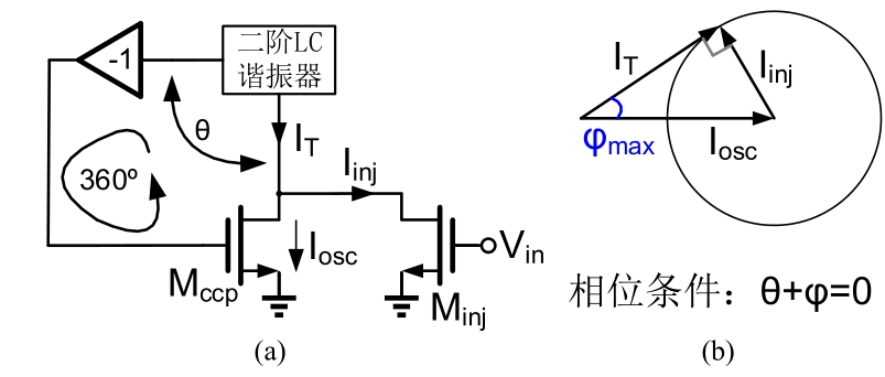
    Fig. 1. (a)Model of half circuit of the ILFM,(b)the corresponding phasor diagram
    Impedance magnitude(a)and phase(b)of the second-order resonator
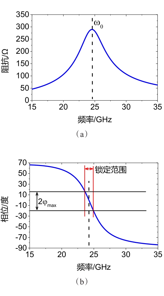
    Fig. 2. Impedance magnitude(a)and phase(b)of the second-order resonator
    Conventional injection-locked frequency tripler
    Fig. 3. Conventional injection-locked frequency tripler
    Proposed ILFT
    Fig. 4. Proposed ILFT
    Second harmonic generation
    Fig. 5. Second harmonic generation
    Waveform at the common source node of the injectors
    Fig. 6. Waveform at the common source node of the injectors
    (a)Transient current waveform at the drains of the injectors, the currents at the drain nodes of the conventional tripler(b)and the proposed tripler(c)
    Fig. 7. (a)Transient current waveform at the drains of the injectors, the currents at the drain nodes of the conventional tripler(b)and the proposed tripler(c)
    The locking ranges corresponding to the two types of injection structure
    Fig. 8. The locking ranges corresponding to the two types of injection structure
    The transformer-based fourth-order tank
    Fig. 9. The transformer-based fourth-order tank
    Dimension of the transformer in the resonator
    Fig. 10. Dimension of the transformer in the resonator
    Inductance and coupling coefficient of the transformer in the resonator
    Fig. 11. Inductance and coupling coefficient of the transformer in the resonator
    Impedance magnitude(a)and phase(b)of the second-order and fourth-order resonator
    Fig. 12. Impedance magnitude(a)and phase(b)of the second-order and fourth-order resonator
    Layout of the proposed ILFT
    Fig. 13. Layout of the proposed ILFT
    Spectrum at 7.8 GHz input frequency
    Fig. 14. Spectrum at 7.8 GHz input frequency
    Sensitivity curve
    Fig. 15. Sensitivity curve
    Single-ended output amplitude and power
    Fig. 16. Single-ended output amplitude and power
    Harmonic rejection ratios(HRRs)
    Fig. 17. Harmonic rejection ratios(HRRs)
    器件参数
    M1-M416 um/ 60 nm
    M5M612 um/ 60 nm
    M7M810 um/ 60 nm
    k10.87
    k20.39
    LDLS1.3 nH
    L1+L1-605 pH
    L2+L2-536 pH
    C1+C1-9 fF
    C2+C2-90 fF
    Table 1. Design Parameters
    三倍频本文*89101112B131420
    A:带有频率调谐,B:二倍频,C:核心面积,D:差分模式

    谐振器

    类型

    4阶2阶2阶2阶2阶4阶9阶4阶-

    输出频率

    [GHz]

    23609046.12281.93341.119.5

    电源电压

    [V]

    1.21.20.81.21.811.2
    功耗[mW]15.21.865.2-9.2210.514.816.818.8

    注入功率

    [dBm]

    064003.1-40-3

    输出功率

    [dBm]

    >-2D-5.38-3.8--2.88-5.96>-500.88D-

    锁定范围

    [GHz]/[%]

    19.2-27.6

    /35.9

    59.30-60.72

    /2.4

    85-95.2A

    /11.3

    42.75-49.5A

    /14.6

    21.38-23.37A

    /8.89

    69.2-81.9A

    /31

    22.8-43.2

    /62%

    33.9-48.2

    /34.8

    18-21.9

    /19.5

    工艺

    65 nm

    CMOS

    130 nm

    CMOS

    65 nm

    CMOS

    65 nm

    CMOS

    180 nm

    CMOS

    65

    65 nm

    CMOS

    65 nm

    CMOS

    180 nm

    CMOS

    面积[mm20.480.390.09C-0.550.16C0.47-1.34
    Table 2. Performance summary and comparison
    Cao WAN, Quan XUE. A wideband injection-locked frequency tripler[J]. Journal of Infrared and Millimeter Waves, 2022, 41(3): 573
    Download Citation