
Xian-guang FAN, Yan-rui HUANG, Long LIU, Ying-jie XU, Xin WANG. An Interpolation Method for Raman Imaging Using Voigt Function[J]. Spectroscopy and Spectral Analysis, 2022, 42(5): 1478
- Spectroscopy and Spectral Analysis
- Vol. 42, Issue 5, 1478 (2022)
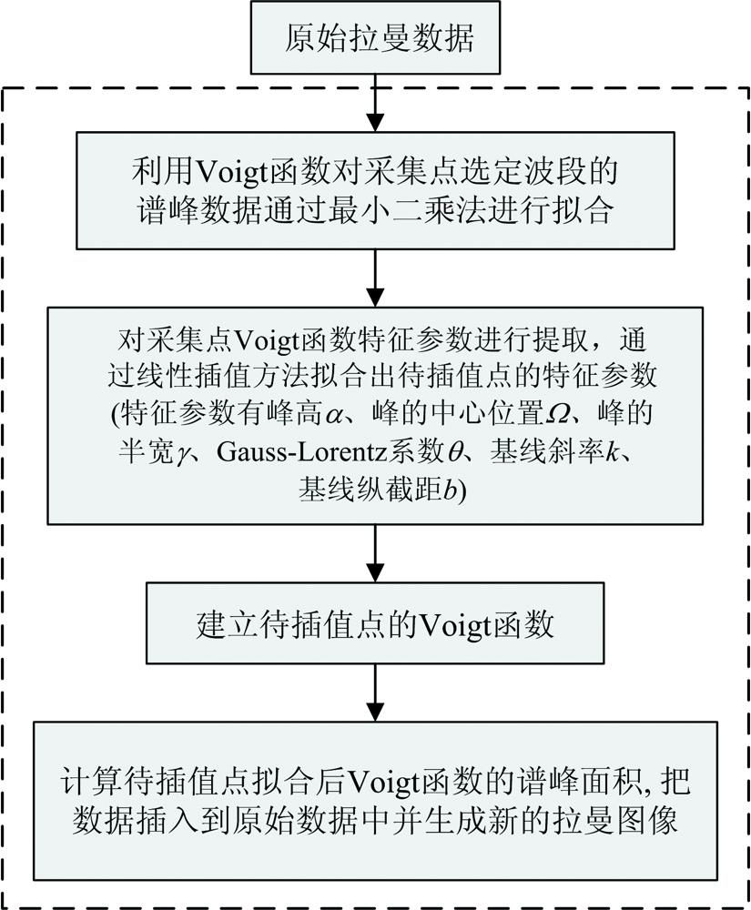
Fig. 1. Flow of the proposed interpolation algorithm for Raman imaging
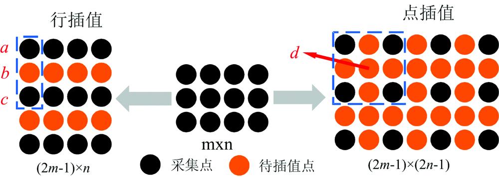
Fig. 2. Interpolation strategy of VFI
Fig. 3. The principle of Voigt function fitting interpolation points with adjacent points in Mode 1
(a): Voigt function of point 1; (b): Voigt function of point 3; (c): Voigt function of point 2
(a): Voigt function of point 1; (b): Voigt function of point 3; (c): Voigt function of point 2
Fig. 4. Experimental comparison image of tablet 1 and cell 1 in mode 1
(a): The image to be interpolated of tablet 1 (The spatial resolution is 19×105); (b): The image after interpolating one row in (a) (37×105); (c): The contrast image was collected with the same spatial resolution as (b) (37×105); (d): The image to be interpolated of cell 1 (The spatial resolution is 19×189); (e): The image after interpolating one row in (d) (37×189); (f): The contrast image was collected with the same spatial resolution as (e) (37×189)
(a): The image to be interpolated of tablet 1 (The spatial resolution is 19×105); (b): The image after interpolating one row in (a) (37×105); (c): The contrast image was collected with the same spatial resolution as (b) (37×105); (d): The image to be interpolated of cell 1 (The spatial resolution is 19×189); (e): The image after interpolating one row in (d) (37×189); (f): The contrast image was collected with the same spatial resolution as (e) (37×189)
Fig. 5. Experimental comparison image of tablet 1 and cell 1 in mode 2(a): The image to be interpolated of tablet 1 (The spatial resolution is 19×53); (b): The image after interpolating one point in (a) (37×105); (c): The contrast image was collected with the same spatial resolution as (b) (37×105); (d): The image to be interpolated of cell 1 (19×95); (e): The image after interpolating one point in (d) (37×189); (f): The contrast image was collected with the same spatial resolution as (e) (37×189)
Fig. 6. Compound histogram of interpolated one line/one point Raman image and same spatial resolution contrast Raman image of tablet 1 and cell 1 in two modes
(a): Compound histogram of tablet 1 in mode 1; (b): Compound histogram of cell 1 in mode 1; (c): Compound histogram of tablet 1 in mode 2; (d): Compound histogram of cell 1 in mode 2
(a): Compound histogram of tablet 1 in mode 1; (b): Compound histogram of cell 1 in mode 1; (c): Compound histogram of tablet 1 in mode 2; (d): Compound histogram of cell 1 in mode 2
Fig. 7. Raman images of tablet 1 and cell 1 interpolated by VFI with different number of interpolations in mode 1
(a):Table 1 interpolates 3 lines of Raman image (145×105); (b): Table 1 interpolates 7 lines of Raman image (289×105); (c): Cell 1 interpolates 3 lines of Raman image (145×189); (d): Cell 1 interpolates 7 lines of Raman image (289×189)
(a):
Fig. 8. Raman images of tablet 1 and cell 1 at different scanning intervals and after interpolation in mode 1
(a): Raman image of tablet 1 (The spatial resolution is 9×10⁵); (b): Raman image of tablet 1(5×10⁵); (c): Raman image of cell 1(9×189); (d): Raman image of cell 1(5×189);(e): Interpolated Raman image of tablet 1 (37×105); (f): Interpolated Raman image of tablet 1 (37×105);(g): Interpolated Raman image of cell 1(37×189); (h): Interpolated Raman image of cell 1(37×189)
(a): Raman image of tablet 1 (The spatial resolution is 9×10⁵); (b): Raman image of tablet 1(5×10⁵); (c): Raman image of cell 1(9×189); (d): Raman image of cell 1(5×189);(e): Interpolated Raman image of tablet 1 (37×105); (f): Interpolated Raman image of tablet 1 (37×105);(g): Interpolated Raman image of cell 1(37×189); (h): Interpolated Raman image of cell 1(37×189)
Fig. 9. Diagram of component information loss
(a): Raman image of cell 1 (The spatial resolution is 37×105); (b) Raman image of cell 1(19×105); (c): Interpolated Raman image of (b)
(a): Raman image of cell 1 (The spatial resolution is 37×105); (b) Raman image of cell 1(19×105); (c): Interpolated Raman image of (b)
|
Table 1. Histogram Euclidean distances and SSIM values for the two samples

Set citation alerts for the article
Please enter your email address
© Copyright 2018-2021 | Chinese Laser Press. All Rights Reserved 沪ICP备15018463号-20