
Xubao He, Xiaoming Xi, Hanwei Zhang, Xiaolin Wang, Xiaojun Xu. Research Progress of Fiber Laser Spectral Combining Based on Dichromatic Mirror[J]. Laser & Optoelectronics Progress, 2021, 58(9): 0900004
- Laser & Optoelectronics Progress
- Vol. 58, Issue 9, 0900004 (2021)
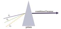
Fig. 1. Diagram of prism-based spectral combining
![Prism-based combiner and optimization example of combiner[26]. (a) Prism-based combiner; (b) optimization example of combiner](/richHtml/lop/2021/58/9/0900004/img_2.jpg)
Fig. 2. Prism-based combiner and optimization example of combiner[26]. (a) Prism-based combiner; (b) optimization example of combiner
Fig. 3. Diagram of spectral combining based on reflective diffraction grating
Fig. 4. Top view of structure of three-channel dual-grating-based spectral combining, and side view of 1070 nm MOPA laser system in vertical direction[33]. (a) Top view of structure of three-channel dual-grating-based spectral combining; (b) side view of 1070 nm MOPA laser system in vertical direction
Fig. 5. Diagram of dual-beam spectral combining optical system based on metal film reflective diffraction grating, and combined power and combined efficiency[34]. (a) Diagram of dual-beam spectral combining optical system based on metal film reflective diffraction grating; (b) combined power and combined efficiency
Fig. 6. Dichromatic mirror spectral combining
Fig. 7. Diagram of spectral combining based on reflective volume Bragg grating[35]
Fig. 8. Four-channel beam combining system based on reflective volume Bragg grating[36]
Fig. 9. Diagram of high-brightness spectral combining system for high-power laser[37]
Fig. 10. Structure of multiplexer[38]
Fig. 11. Characteristics of multiplexing of filter[38]
Fig. 12. Diagram of experimental setup[39]
Fig. 13. Spectra of input beam and output beam of three channels, and beam intensity distribution after beam combining[39]
Fig. 14. Diagram of experimental setup and transmission curve[40]. (a) Diagram of experimental setup; (b) transmission curve,showing 3 nm spectral bandwidth and steep edges
Fig. 15. Relationship among pump power, combined output power, and combined beam quality(illustration shows spot pattern at output power of 208 W)[40]
Fig. 16. Structural diagram of hybrid beam combining system[14]
Fig. 17. Experimental setup diagram of spectral combining scheme based on dichromatic mirror[42]
Fig. 18. Structural diagram of dichromatic mirror, and reflectance curves of dichromatic mirror under different surface roughness[42]. (a) Structural diagram of dichromatic mirror; (b) reflectance curves of dichromatic mirror under different surface roughness
Fig. 19. Relationship between output beam quality and current[43]. (a) Mx2; (b) My2
Fig. 20. Passive compensation scheme of thermal lens[43]
Fig. 21. BQD coefficient varies with output power under different conditions[43]. (a) Horizontal direction; (b) vertical direction
Fig. 22. Experimental setup diagram of spectral combining based on dichromatic mirror[44]
Fig. 23. Relationship among output power, combining efficiency, and input power, and emission spectrum at 6.2 kW[44]. (a) Relationship among output power, combining efficiency, and input power; (b) emission spectrum at 6.2 kW with resolution bandwidth of 0.2 nm
Fig. 24. Relationship between output beam quality and current (insets show energy distributions at focus position of 1070 nm laser and combined laser at maximum output power)[44]. (a) Mx2; (b) My2
|
Table 1. Advantages and disadvantages of different spectral combining methods

Set citation alerts for the article
Please enter your email address
© Copyright 2018-2021 | Chinese Laser Press. All Rights Reserved 沪ICP备15018463号-20