Historically, nonlinear optical phenomena such as spectral broadening by harmonic generation have been associated with crystals owing to their strong nonlinear refractive indices, which are in the range of . This association was also the result of the limited optical power available from early lasers and the limited interaction length that the laser–crystal interaction architecture could offer. Consequently, these limitations disqualified a large number of materials whose nonlinear coefficient is lower than as suitable materials for nonlinear optics applications. For example, it is a common practice in most of optical laboratories to consider ambient or atmospheric air as a “nonlinear optically” inert medium due to its very low nonlinear coefficient () and low density. Today, the wide spread of high-power ultra-short pulse lasers on one hand, and low transmission loss and high-power handling of Kagome hollow-core photonic crystal fiber on the other hand, provide the necessary ingredients to excite strong nonlinear optical effects in practically any gas media, regardless of how low its optical nonlinear response is. By using a single table-top 1 mJ ultra-short pulse laser and an air exposed inhibited-coupling guiding hollow-core photonic crystal fiber, we observed generation of supercontinuum and third harmonic generation when the laser pulse duration was set at 600 fs and Raman comb generation when the duration was 300 ps. The supercontinuum spectrum spans over and exhibits a typical spectral-density energy of 150 nJ/nm. The dispersion profile of inhibited-coupling hollow-core fiber imprints a distinctive sequence in the supercontinuum generation, which is triggered by the generation of a cascade of four-wave mixing lines and concluded by solitonic dynamics. The Raman comb spans over 300 THz and exhibits multiple sidebands originating from vibrational and ro-vibrational Raman transitions. With the growing use of hollow-core photonic crystal fiber in different fields, the results can be applied to mitigate air nonlinear response when it is not desired or to use ambient air as a convenient nonlinear medium.
1. INTRODUCTION
Historically, transparent crystals and then glasses have strongly been associated with nonlinear optics [1]. Their high density and their strong laser-induced nonlinear polarization density meant a large nonlinear refractive index coefficient (typically ), enabling generation of nonlinear effects with relatively low laser power levels and short interaction length [2]. This is exemplified by the seminal demonstration of second-harmonic generation in ruby by Franken [3] and the original supercontinuum (SC) generation in borosilicate BK7 glass by Alfano and co-workers [4]. Since these early works, nonlinear optics has continuously been driven by the progress in two fields: the optical material field and the laser field. For example, research on optical materials enabled us to identify a large number of alternative nonlinear optical materials including non-solid phase materials such as liquids [5], whose nonlinear indices could be as high as those of crystals. Furthermore, the development of high-intensity and ultra-short-duration lasers enabled the demonstration of SC in high-pressure gases [6].
Another landmark in the progress of nonlinear optics is illustrated by the generation of over one-octave-wide SC in silica-core photonic crystal fibers (PCFs) [2,7]. This created a new paradigm whereby the main driving contribution to the enhancement of nonlinear effects is provided no longer by a new progress in lasers or materials but by the waveguide configuration of the laser–matter interaction. The extremely small effective area and long interaction length offered by this PCF configuration enabled the excitation of strong optical nonlinearities with laser peak power levels that are orders of magnitude lower than what was previously possible in the previously well-explored silica glass material [7]. This ability to generate strong optical nonlinear effects with low power levels has been extended to gases and liquids with the advent of hollow-core photonic crystal fiber [8,9]. Among the recent demonstrations of such strong optical nonlinearities at low light levels, we count the generation of several-octave SC [10] and Raman combs [11] in hydrogen-filled Kagome hollow-core PCF (HC-PCF). This fiber technology allows meters-long and micrometer transverse laser beam confinement with strong light/gas interaction when its core is filled with gas. The various core/cladding designs of the inhibited-coupling HC-PCF family offer a large tunability in terms of core size, dispersion value, and profile.
Following up on our previous work [12], we show in this paper that very weakly nonlinear optical materials can also be used within a simple and table-top experimental setup as a platform for the generation of strong and multifarious nonlinear optical effects. We choose atmospheric air as a material for this purpose. The choice is motivated by the fact that air is ambient and requires no special exploitation engineering, as well as by the fact that air, except for some applications in high optical field, has until now been mostly considered as a nonlinear optically inert medium due to its very low nonlinear coefficient () and its low density. Furthermore, this work is enabled and motivated by two major advances. The first advance concerns the dramatic progress in power scaling of ultra-short-pulse (USP) lasers, which followed the invention of the chirped pulse amplification (CPA) technique [13,14]. Today, such lasers can offer compact solutions with a large dynamic range in repetition rate spanning from kilohertz (kHz) to megahertz (MHz) and intensity levels in the range of petawatt per square centimeter (). The second advance is associated with the development of inhibited-coupling (IC) optical guidance, which led to the seminal introduction of hypocycloid core contour (i.e., negative curvature) in hollow-core fibers [15]. Today, IC Kagome HC-PCF with hypocycloid core contour combines low loss [16–19], large optical bandwidth, and record USP energy handling reaching the millijoule (mJ) level [20].
Sign up for Photonics Research TOC. Get the latest issue of Photonics Research delivered right to you!Sign up now
Here, we report on the use of a single table-top experimental setup consisting of a USP laser and two atmospheric air-filled IC Kagome fibers to generate a 300 THz wide Raman comb with 70 THz spacing, a broad SC with a record energy spectral density of 150 nJ/nm, and third-harmonic generation. The dynamics of the SC generation are described, resulting from varied phenomena such as four-wave mixing (FWM), third-harmonic generation (THG), and soliton formation.
2. EXPERIMENTS
A. Experimental Setup
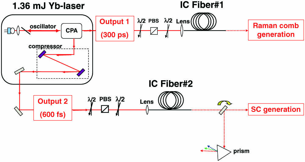
The experimental setup used for the different experiments reported in this paper is shown in Fig. 1. A single, table-top Yb-based CPA laser, operating at 1030 nm, emits up to 1.36 mJ energy pulses at 1 kHz repetition rate. The laser can emit either 300 ps duration pulses through a first channel labelled “output 1” in Fig. 1 or 600 fs pulses through another channel labelled “output 2.” The laser beam from each channel is coupled into an IC Kagome HC-PCF.
Figure 1.Experimental setup. Table-top Yb laser (1.36 mJ, 1 kHz repetition rate) composed of two output channels (“output 1” corresponding to 300 ps pulses, and “output 2” corresponding to 600 fs pulses) coupled into two different IC Kagome HC-PCFs.
The IC HC-PCFs were simply exposed to the ambient air. This air-filling configuration drastically simplifies the laser beam injection module that is composed just of a lens and a translation stage. The launching power is controlled by the use of two half-wave plates and a polarizing beam splitter. The air is gas mixture having a pressure of 1 atm, with the main constituents being nitrogen molecules (78% in volume) and oxygen molecules (21% in volume) and to a lesser extent argon (1% in volume).
Considering only the nitrogen and oxygen molecules, the nonlinear polarization in both molecules is based on third-order susceptibility, and it can be induced either by the electronic Kerr effect or stimulated Raman scattering (SRS). The Kerr effect leads to the index-change-induced field phase variation and manifests itself in self-phase modulation (SPM) spectral broadening, FWM, and THG. SRS process results from a resonant response of the third-order susceptibility and manifests itself via conversion of the pump frequency to discrete spectral lines with frequencies down-shifted (Stokes lines) or up-shifted (anti-Stokes lines) by the Raman transition frequency . Here, is a positive integer corresponding to the Raman order of the generated Stokes and anti-Stokes lines.
Table 1 summarizes the main ambient air material properties that are relevant in the laser pulse propagation nonlinear optical dynamics. The table shows that atmospheric air has a nonlinear refractive index of [21,22]. Furthermore, the table shows the steady-state Raman gain coefficient for both and . Here, is defined from the exponential expression of the first-order Stokes intensity under steady state , where is the pump laser intensity and is the fiber length. Both molecules exhibit a vibrational Q(1) Raman transition with a respective resonance frequency of 69.9 THz and 46.6 THz. These resonances have a gain coefficient of 35 cm/TW and 22 cm/TW, respectively, and a dephasing time of 7.1 ps for and 5.9 ps for [23]. Thus, one would expect the SRS process to be mainly governed by molecules. The table also shows that atmospheric air nitrogen exhibits several rotational Raman lines (corresponding to a transition from the rotational quantum number to ) with the comparable Raman resonance frequencies and gain coefficients [24]. For these transitions, the dephasing times are deduced from Ref. [25]. Similarly, also has rotational Raman transitions; however, we deliberately ignore them because of the relatively low density of .
Molecules
Raman Frequency Shift (THz)
gss(10−3cm/GW)
T2(ps)
n2(10−19cm2/Wat 1 bar)
Air
10
N2
Q(1)
69.9
35
7.1
8
S(6)
1.8
6.3
∼200
S(8)
2.3
7.3
S(10)
2.8
7.2
S(12)
3.2
6.1
O2
46.6
22
5.9
30
Table 1. Kerr and SRS Coefficients of Main Atmospheric Air Gases
It is noteworthy to recall that the maximum found in air nitrogen or oxygen is several hundred times lower than that found in hydrogen molecular gas.
Due to the broadband operation and Raman-active filling gas, the considered experimental setup supports manifestation of a number of nonlinear effects: Raman gain, self-phase modulation, FWM, and THG. The relative impact of these effects is determined by their characteristic lengths: , , , and , correspondingly. The shorter the characteristic length, the earlier the associated nonlinear process manifests itself. In addition to the above intrinsic properties of the molecules, the competition between these four effects in air strongly depends on the pump pulse duration and is also influenced by the fiber dispersion as detailed below. We note parenthetically that for a fixed pump power the intensity is higher for a smaller fiber cross section, and all the characteristic lengths are correspondingly shorter; this dependence is exactly identical for all four effects.
The characteristic length for the Raman effect is given by [26–28]Here, the factor 25 corresponds to the necessary Raman net gain to reach the stimulated scattering. The dependence of the Raman gain correction factor on pulse duration , the molecular dephasing rate , the fiber length , and the effective area is given by where is the pump intensity. One can see that Raman effect becomes slightly stronger for longer pulses and manifests itself earlier in propagation. In addition, the dynamics of the Raman effect are influenced by the dispersion due to the role of walk-off.
In order to define the characteristic length for the SPM , we need to choose the spectral width to be reached at . For a dominating Raman effect, the Raman gain will result in generation of a clear comb with period of offset from the pump frequency. On the other hand, if SPM contribution is dominating over the Raman effect, the spectral broadening will extend the spectrum to before sidebands develop. Therefore, for our aims we define as the length at which the spectral width reaches : It is clear that the relative role of the SPM increases with decreasing duration, while the dependence of on is weaker. From comparison of and , we expect that SPM will be the dominating mechanism for short pulses, while for longer pulses Raman effect will take the leading role. The group velocity dispersion can significantly influence the SPM process, resulting in pulse elongation and saturation of spectral broadening for normal group velocity dispersion, or resulting in soliton dynamics and SC generation for anomalous dispersion (AD).
For FWM, the characteristic length is given by [29]In addition, efficient FWM is only possible if the phase-matching condition is satisfied, where and are the signal and idler frequencies, correspondingly.
Finally, the characteristic length for the THG () is For our conditions, both FWM and THG will manifest at propagation lengths longer than . However, due to the significant spectral offset from the pump frequency , which is given by for FWM and even larger value of for THG, the corresponding spectral peaks will still be discernible in the spectrum.
Table 2 provides values of characteristic lengths of the different above-mentioned nonlinear effects (Raman gain, SPM, FWM, and THG) for a representative input pulse intensity of , which corresponds to an energy of 800 μJ at 600 fs. One can clearly see that for the shortest pulse duration (600 fs) the dominant effect is the SPM, whereas for longer pulses (300 ps) Raman effect dominates with a characteristic length of 6.5 mm. The two other effects are dependent on phase-matching conditions and lead to an FWM length of 0.6 cm and a THG length of 15 cm for perfect phase-matching.
Pulse Width
LR (cm)
LSPM (cm)
LFWM (cm)
LTHG (cm)
600 fs
15
1.3
∼0.6
15
300 ps
0.65
600
∼0.6
15
Table 2. Characteristic Lengths of Nonlinear Effects: Raman Gain, Self-Phase Modulation, Four-Wave Mixing, and Third Harmonic Generation, for Input Intensity
Both fibers used are IC guiding Kagome-lattice HC-PCFs with hypocycloid core. Figure 2(a) shows the scanning electron microscope (SEM) images of the two fibers. They are based on a seven-cell core defect design with a negative curvature parameter equal to 1 (see Ref. [16] for definition of ). Their inner core radius is equal to 30 μm, corresponding to a mode field diameter (MFD) of 42 μm. However, the fibers have different silica strut thicknesses so that they provide specific transmission and dispersion spectra. This is illustrated in Figs. 2(b) and 2(c), showing the two fibers’ spectra of transmission over a 4 m long fiber section (shaded grey curves), the transmission loss (blue curves), and the effective index of the fiber-core fundamental mode (black curves).
Figure 2.(a) SEM images of the cross section of the two IC fibers used. Transmission (shaded grey curves), loss (blue curves), and effective index of the core fundamental mode (black curve) spectra for (b) Fiber #A and (c) Fiber #B. Normal and anomalous dispersion regimes in different transmission bands identified by ND and AD, respectively.
The fiber transmission and loss spectra exhibit a series of low-loss transmission bands separated with non-guiding bands centered at wavelengths related to the strut thickness by . Here, and are the silica-strut thickness and index, respectively, and is a positive integer. The non-guiding bands correspond to a strong transverse-matching-induced coupling between the core mode and the silica cladding modes [30]. Over our measurable spectral range of 400–1750 nm, Fiber #A exhibits 5 transmission windows, its second-order transmission band exhibiting an edge centered at 1250 nm. This is consistent with the measured strut thickness of 1250 nm. This thickness has been chosen to optimize the number of generated Stokes lines. At the operating 1030 nm laser wavelength, the fiber has transmission loss of 60 dB/km. Fiber #B has a silica-strut thickness of 1100 nm, and accordingly its transmission spectrum exhibits transmission bands that are blue-shifted by 10% relative to those of Fiber #A. Fiber #B has a loss value of 200 dB/km at 1030 nm.
The black curves in Figs. 2(b) and 2(c) show the numerically calculated effective index of the fiber-core fundamental mode for Fiber #A and Fiber #B, respectively. Similar to the transmission and loss spectra, because of the coupling between the core mode with the cladding modes near the wavelengths , the core fundamental-mode chromatic dispersion exhibits discontinuities in the non-guiding regions with an S-like profile at each transmission band [16,30]. As a result, each transmission window is segmented into a normal dispersion (ND) region and AD region [see the shaded regions in Figs. 2(b) and 2(c)].
For the experiments developed below, a 3 m long piece of Fiber #A is excited by 300 ps pulses. Here the laser wavelength (represented by dashed line in Fig. 2) is located close to the zero-group velocity dispersion (ZGVD) of the second higher-order transmission band. Furthermore, a 3.8 m long piece of Fiber #B is excited by the 600 fs pulses, and the laser wavelength is located in the AD region of the second higher-order transmission band.
3. RESULTS
A. Raman Comb Generation
Figure 3 shows the evolution of the output spectrum with the input energy in a 3 m long piece of Fiber #A. The map shows the development of distinct spectral lines with a Raman comb that spans over a wide spectrum range, up to (from 600 to 1375 nm), with a comb spacing of 70 THz and evolving as follows.
Figure 3.(a) Raman comb generated at the output of IC Fiber #A for a 300 ps laser pulse duration. Evolution of the 3 m long air-filled IC Fiber #A output spectrum. (Top) Output spectrum for input energy of 1.36 mJ. The input pulse is shown for comparison. (Right) Transmission coefficient versus input energy. (b) Rotational response of the line.
The first two lines appear at an energy of 650 μJ (corresponding to a transmitted energy of 530 μJ) that correspond to the first Stokes line (noted ) and first anti-Stokes line of (noted ) vibrational Raman resonance Q(1). The second anti-Stokes line appears for an input energy of 750 μJ, and then another one for 1200 μJ. The energy is mainly distributed between the pump, , and . We can see that each line presents a spectral feature characterized by spectral broadening increasing with the input energy, attributed in this case to the rotational response of the nitrogen (in the present graph, the S6 system). We also observe the S8 lines, though not as clearly as the S6 lines. This fact is due to the combination of the smaller strength of the S8 Raman transition and the resolution of the optical spectrum analyzer (OSA).
Figure 3(b) shows a zoom of the line at the maximum output energy where the different rotational lines of the second vibrational line are identified.
The graph at the top of Fig. 3 represents the generated spectrum at the maximum 1.36 mJ launched energy. For this input energy laser beam, an output energy of 1.03 mJ is measured, corresponding to an impressive 75% transmission. The evolution of the transmission coefficient with the input energy is plotted on the right side of the map. One can see that for input energies up to 700 mJ, the transmission is equal to 83% and drops gently after the comb onset, reaching 75% for the maximum energy. This reveals that the Raman comb dynamics do not imply significant loss. Finally, the comb structure of the spectrum shows an insignificant to zero effect from Kerr nonlinearity, even at energy value as high as 1.03 mJ, which contrasts with those obtained with 6 ps [31].
B. Supercontinuum Generation
The excitation of the 3.8 m long piece of Fiber #B by 600 fs pulse duration presents a completely different spectral dynamic. The peak power corresponding to this excitation is 3 orders of magnitude higher than the previously studied one, with a maximum value reaching 1.8 GW. Here, the pulse propagation dynamics are dominated by SPM and solitonic dynamics leading to a petahertz ()-wide SC confined within the transmission bands of the HC-PCF. The right-hand side of the map in Fig. 4 shows the transmission coefficient after the 3.8 m-long piece. At the SC onset, the transmission efficiency drops from 70% to 30%.
Figure 4.(a) SC generated at the output of IC Fiber #B for a 600 fs laser pulse duration. Experimental evolution of the 3.8 m long air-filled IC Fiber #B output spectrum. (Top) Output spectrum for input energy of 840 μJ. The input pulse is shown for comparison. (Right) Transmission coefficient versus input energy. (b) Dispersed beam of the SC generated at the output of the IC Fiber #B.
At input energy of 840 μJ, the output energy of the SC was measured to be 155 μJ. The corresponding energy spectral density reached a record value of 150 nJ/nm, which is 2 orders of magnitude higher than that of a SC based on fiber laser sources [32].
The dynamics of the SC generation have been studied theoretically by carrying out numerical simulations using the generalized nonlinear Schrödinger equation, augmented by the equations describing the dynamics of the Raman polarization. The group velocity dispersion to all orders, the wavelength-dependent loss, the Kerr effect, the Raman scattering, and the quantum noise were included in the simulation. Figure 5 shows the theoretical evolution with the input energy of the output spectrum for the case of a fiber length of 20 cm. This length has been chosen to clearly see and identify the multiple processes responsible before the SC onset. The laser pump first induces a generation of the third harmonic at 343 nm under non-phase-matched conditions. However, this THG has not been observed experimentally on the fundamental mode but on a higher-order one (see the next section). Then (at 200 μJ) two new frequencies (denoted by and ) appear through the FWM process. These new frequencies act as a seed to create a cascade of FWM combination, allowing access to all of the transmission bands of the fiber due to the specific evolution of the effective index of the core mode [graph at the bottom of Fig. 5(b)].
Figure 5.(a) Theoretical spectral evolution of the 20 cm long air-filled IC Fiber #B output spectrum. (Top) Output spectrum for input energy of 840 μJ. The input pulse is shown for comparison. (b) Output fiber theoretical spectral evolution with the input energy (100, 200, and 400 μJ) for a fiber length of 20 cm. (Bottom) Phase mismatch curve as a function of the idler/signal wavelengths ( and ). (c) Theoretical temporal pulse profiles for two input energies: 20 μJ and 500 μJ.
After the development of the FWM sidebands, at higher energy than 400 μJ, the temporal profile becomes highly modulated as shown in Fig. 5(c). It features many isolated spikes in the temporal profile, which remain roughly unchanged with further propagation. We have evaluated the spectral contents of the strongest of these spikes and found that its central frequency lies around the pump frequency in the AD region. Therefore, we conclude that the spikes have a solitonic nature, and the late stage of the SC generation is governed by soliton dynamics and possibly by the associated generation of the non-solitonic radiation.
The phase mismatch will additionally strongly influence the efficiency of both the FWM and the THG. In Fig. 5(b), we present the phase mismatch as a function of the idler/signal wavelength considering the fundamental core mode as where , with the wavenumber and given by Ref. [33].
One can see that the position of the phase-matched wavelengths is mainly defined by the transmission band edges. In addition, the contribution of the nonlinear term in the phase mismatch is significant, changing the number of the phase-matching wavelength and shifting it.
C. High Harmonic Generation
The last phenomenon that has been explored is the generation of the third harmonic. First, the conditions of phase matching between the fundamental core mode and high-order modes have been studied theoretically [see Fig. 6(a)]. Since the pump beam is characterized by azimuthal symmetry, the third-harmonic polarization induced by pump light is also azimuthally symmetric; therefore, only phase matching between the fundamental mode and azimuthally symmetric modes was considered. To evaluate the effective refractive index () of IC Kagome fiber at the third-harmonic frequency, we consider for this section the dispersion curves of , , , and of Fiber #B using analytical formula for capillaries by Zeisberger et al.[33].
Figure 6.(a) Phase mismatch versus the mode number . (b) Experimental spectral evolution with input power, up to 175 mW, of the THG at the output of a 30 cm long air-filled IC Fiber #B.
The phase mismatch between the fundamental mode and for THG can be written as where are propagation constants of a high-order mode, is the nonlinear coefficient, are the cross-phase-modulation overlap coefficients, and is the peak power.
Figure 6(a) shows dependence of the phase mismatch on mode number . Note that in our case this mismatch is weakly dependent on the peak power. One can see that the smallest mismatch is predicted for the and modes. The radial distribution of intensity for the mode is characterized by zero intensity at 0.44 and at , while distribution of intensity for the mode has three zeros: at 0.28, at 0.64, and at .
The THG has been experimentally observed and studied as follows. The input pulses from the 1030 nm laser were coupled in a 30 cm long piece of Fiber #B, and the polarization was controlled by a half-wave plate to maximize the coupling efficiency. The conversion of the pump has been measured for an input power from 5 to 175 mW, and the output fiber spectral evolution around 343 nm is shown in Fig. 6(b). We observe the onset of THG at and increase of the TH intensity between 155 and 175 mW. The inset picture at the top left of Fig. 6(b) shows the observed light at a distance of 20 cm from the output tip of the fiber. The intensity profile of the observed mode is a mixture of the profiles of the and modes, in agreement with the theory developed above. We interpret the slight azimuthal modulation of the intensity profile as a result of competing cascaded processes related to FWM.
4. CONCLUSIONS
We have experimentally demonstrated the generation of several nonlinear processes in air-filled IC HC-PCF. By using the pump pulse durations of 600 fs and 300 ps, we have observed an intense and broad SC and a Raman comb, respectively. Finally, THG at 343 nm has been measured for 600 fs input pulses. These experimental results have been supported and corroborated by theoretical results.
Acknowledgment
Acknowledgment. The authors thank the PLATINOM (Xlim) platform for their help in the fiber fabrication.
[12] B. Debord, F. Gérôme, C. Honninger, E. Mottay, A. Husakou, F. Benabid, F. Benabid, F. Benabid. Milli-Joule energy-level comb and supercontinuum generation in atmospheric air-filled inhibited coupling Kagome fiber. CLEO: 2015 Postdeadline Paper Digest, JTh5C.4(2015).
[15] Y. Wang, F. Couny, P. J. Roberts, F. Benabid. Low loss broadband transmission in optimized core-shape Kagome hollow-core PCF. Conference on Lasers and Electro-Optics, CPDB4(2010).